
All three of the books mentioned in the lead-up to this page presented their
own versions of the two-pole electric motor model. There isn't much room for
variation; we're talking basically about a straight electromagnet (the
armature), mounted centrally on a spindle with its two coil-ends
connected to some kind of commutator (an automatic rotary switching
device) and mounted in a horse-shoe shaped electromagnet called the
field-magnet. Two springy contacts called brushes push against
the commutator, one on each side, thus facilitating the automatic switching
as the armature/commutator combination rotates.
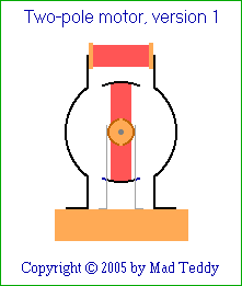
The usual arrangement is something like this (end view):
The models illustrated in both Morgan's and Bulman's books are of this type.
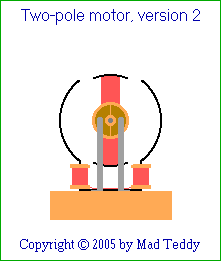
However, the version in book X (the first of the three that I saw) had a
couple of minor differences which perhaps add a bit of interest:
The field magnet is inverted, with its ends up in the air rather than
screwed to the base. The central part of the field magnet is attached to the
base instead, and the coil is wound in two halves on the lower portions of
each leg, close to the base. Importantly, the wire must cross diagonally
over the horizontal central part from one side of the field magnet to the
other, so that the two windings reinforce each other and act as a single
winding - rather than opposing each other and thus tending to cancel each
other's magnetic fields.
The commutator, instead of being made from two semi-cylindrical pieces, is
made from a brass washer sawn in half, with the halves glued to a disc made
from insulating material (hardboard or similar) and the whole thing mounted
on the spindle. Then the brushes, instead of pushing inwards toward the
spindle, push the commutator/armature/spindle combination (i.e. the
rotor) back toward the rear support, where a washer is inserted.
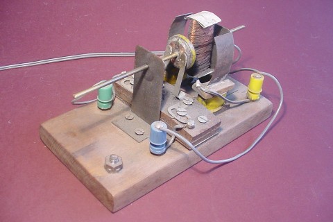
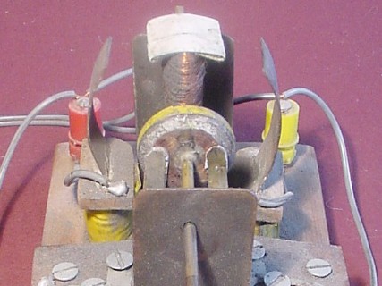
Well, that's the version that my Dad and I built - and here's the result!
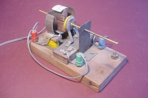
Here's another view:
This view is a straight-on picture of the commutator and brushes.
You've probably noticed that it looks rather scruffy; it appears to be
covered in a layer of grey dust. Well, that's quite true - it is!
Like most of my projects made a long time ago, this has undergone various
adjustments in an effort to improve its performance. Motors with moving
contacts are notorious for damage to the brushes, and even the commutator,
caused by friction and (especially) sparking. This is a real problem with a
two-pole motor, in which there is only one armature winding and hence only
two commutator segments, so that every half-turn a momentary short-circuit
occurs between the brushes. The ends of the brushes were gradually being
burned away by the excessive sparking thus generated; and at some stage I
reduced the problem by melting some solder onto them, and carefully shaping
the resulting blobs with a file.
Originally, when we made the commutator, putty was used to pad around and
between the two halves of the brass washer. Over time, some of the putty was
scratched away by friction (and by me, trying anything to improve the
performance - making it worse, usually).
A few years ago I made a significant improvement by scratching most of the
putty out and carefully replacing it with Araldite, an epoxy glue which
sets very hard. I allowed a small amount of it to cover the very ends of the
commutator halves in a very thin layer, thus reducing their length by a
small amount and also contributing slightly to the overall frictional
effects. This solved the shorting problem, but of course it reduced the
machine's total power. (Any attempt to improve the performance of an
electrical device with moving contacts is always a balancing act!)
So I dropped some powdered lubricating graphite into the contact points
between the brushes and the commutator while the motor was spinning. It
worked beautifully, reducing the friction and making the motor spin really
fast - amazingly, without arcing via the loose graphite powder - but of
course, the graphite puffed up and went all over the place! Hence the rather
grotty appearance of the motor.
I might clean it up a bit someday; but it looks like a messy and tedious
job, and I'm inclined to put that sort of thing off (who isn't?).
You can click
here
to see a 5-second .mpg movie (~477.6Kb) of the motor running off my old
power supply and bridge rectifier. While I try to hold the camera steady, my
son switches the power supply on and then off after a few seconds. (The
motor spins anticlockwise.)
You may have noticed that the motor is "shunt-wound", which means that the
field magnet and the armature are connected in parallel. It's also possible
to connect them in series, giving a "series-wound" motor. I find that this
motor runs best when shunt-wound. If you make your own motor, this is
something you may care to investigate.
Also, I find it works better with DC rather than AC current. This may well
be basically because rectification and smoothing quite simply make more
power available; but there are other subtleties which are worth reading up
on.
Here
is a good link which deals with motors of various kinds, including both AC
and DC (in both shunt-wound and series-wound configurations). Also,
this page
goes into considerable detail - with excellent B&W diagrams - of the
workings of various types of electric motors.
UPDATE, 30th January, 2007
This
Wikipedia article
also describes electric motors of many types, and is well worth a look. It
has an excellent eye-catching animation of a three-phase synchronous
electric motor.
You can click on it to read its creator's comments about it. Of particular
note is the dedication "to year of Nikola Tesla". Apparently, the animation
was published in March 2006, the year of the 150th anniversary of Tesla's
birth. So I'm happy to draw attention to the creative efforts of a kindred
spirit!
UPDATE, 5th July, 2008
I noticed a while back that the animation of the three-phase synchronous
motor (mentioned above) had disappeared from that Wikipedia page. I decided
to leave the link in this page anyway, since it's still worth a look - and
with the hope that the animation might reappear in the page at some stage.
It hasn't - but it has turned up in another Wikipedia page!
(How good is that?!!) I just happened to stumble across it while hunting for
something else.
Here it is, along with lots of very good technical information:
http://en.wikipedia.org/wiki/Three-phase
UPDATE, 20th May, 2017
Yep - you guessed it - that animation has moved again! It's now here:
https://en.wikipedia.org/wiki/Synchronous_motor
Will it move again? Who knows - quite possibly! Or it may disappear altogether...
Right - here's an attempt to "beat the system", as it were: a link to the graphic itself, without going through any other pages! Will this do the trick? Hoping...
https://en.wikipedia.org/wiki/File:3phase-rmf-180f-airopt.gif
My home page
Preliminaries (Copyright, Safety)
My two-pole electric motor (ca. 1966)

 Return to Electromechanical models sub-menu