
My Dad was a civil engineer, but he was also a qualified electrician, having
trained while in the British Royal Air Force during WW2. He had a hobby
interest in things electrical - which is presumably where I get my own
predisposition to such things.
I started to become interested late in primary school. I'd see my Dad
tinkering with some intriguing-looking thing or other, and want to know how
it worked. So we developed a shared interest.
Later, in high-school, when I found some interesting project books in the
school library, he helped me to build some of them. Of course, batteries
don't last long; hence the need for a power supply. So he built one!
Here it is. (You can click on it to see a bigger version.)
It is shown set to its maximum voltage (approximately 20V AC), switched on
with no load.
It plugs into the 240V mains. There is a small torch globe mounted behind a
green transparent cover to indicate power-on. Above the voltmeter are two
terminals, between which is connected a piece of 5-amp fuse wire. The lower
meter is a 5-amp FSD (full-scale deflection) ammeter.
You may have noticed a strange little symbol on each of the meter faces.
It's a stylized "JLW", my Dad's initials, which he liked to put on things
he'd modified in some way, as a little personal touch.
The control on the left is a five-position rotary switch. The settings are
1V, 7V, 14V, 17V, and 20V (approximately). The control on the right is a
rheostat - a wire-wound forerunner to the modern potentiometer.
When I was young, I didn't understand the intricacies of how the controls
worked. I would use the rheostat to achieve a fine-control on the output
voltage, as set by the rotary switch. One day, when my Dad caught me with
the rheostat turned right down (anticlockwise), he nearly freaked out. As a
result of this, I came to vaguely understand that the rheostat could get
HOT, and possibly burn out, at high-current levels. Oh dear! Luckily, no
harm done. My electrical knowledge is at a much higher level now, of course,
and I treat the old thing with a great deal more respect! (In fact, I hardly
ever touch the rheostat at all - I normally just leave it turned fully
clockwise.)
To be honest, I don't know the exact details of the circuit. A while ago, I
decided it was high time I did; so I carefully unscrewed the front panel and
tried to get a look inside. However, I reluctantly gave up on the idea; I
was afraid that disturbing the forty-odd-year-old wiring might cause serious
damage. Without learning much at all, I replaced the cover and decided to
leave well enough alone. If it ever stops working, I'll bite the bullet
then.
The power-supply provides AC only - it does not have a built-in
rectification system. A few years ago, when I wanted a DC supply, I built
a stand-alone full-wave bridge rectifier from parts of an old car
alternator that somebody had junked:
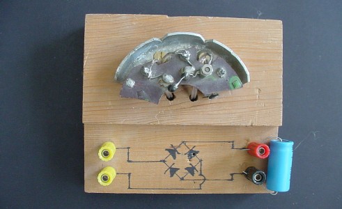
AC from the power supply is input at the left (yellow terminals); DC is
output at the right (red = positive; black = negative). Smoothing is
achieved very simply by a 2200 microfarad, 50V capactior across the output
terminals.
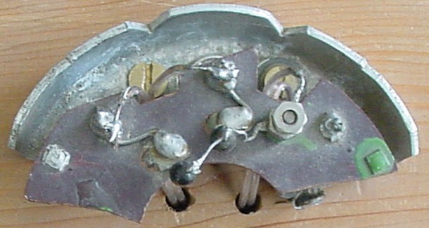
Here is a close-up of the business part of the device (love the blobby
soldering!).
Alternator armatures have three windings, to produce three-phase AC output.
To rectify this to DC, which the car needs, there are six strongly-built
diodes included. The benefit of three-phase rectified output is that it is
quite smooth. For more information on this and related matters, see this
link:
ALTERNATOR SECRETS
I'm not an expert on alternators. I do know that, in addition to the six
"on-board" diodes, at least some alternators also include three "bead"-type
diodes.
My home-made bridge rectifier consists of three "on-board" diodes, one of
which (on the extreme right) is no good (which is presumably why the
alternator was junked in the first place), and two "bead"-type diodes, which
you can see in the lower-central part of the picture. The "on board" diodes
are concealed beneath the dark brown (Bakelite or similar) insulating plate;
you can only see the top connections to them. The four good diodes are
soldered together in the standard bridge configuration.
Theoretically, a smoothed full-wave rectifier like this provides a DC
voltage which is nominally equal to the input AC voltage times the square
root of 2 (~ 1.414). So I should be able to get about 28V DC out of this.
In fact, it provides about 27V DC, which is not too bad at all.
So: that's the power supply that you may see here and there in photographs
of various projects in this site.
I'm well aware of how lucky I am to own such a thing. Modern power supplies
cost quite a lot; and from what I've seen of them in catalogues, many of
them don't appear to be as robust as my old clunker. Few, if any, claim to
be able to provide 27V DC at 5 amps without having a seizure!
UPDATE, Sunday, 1st March 2009
AAAARRGH!
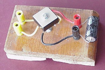
... so I bought a commercial bridge rectifier and made up the unit you see
here.
It works just as well as the old one. Some day, I'll attempt a repair job on
the old one (I have a couple of spare bead diodes from another old
alternator
A TRIBUTE TO MY DAD
My Dad died in 1981, at the age of 57, from cancer. I was 28 years old at
the time.
We didn't always get on too well. There was a classic "generation gap"; he
had grown up during the depression years, and I grew up in the 1960's. It
was a recipe for
anguish,
all over the western world.
It's possible, if one is not careful, to dwell on the negatives too much.
At this time in my life, I think I've dealt reasonably well with the main
issues, and am now able to see the whole era in its historical perspective.
Sometimes, of course, I still feel flashes of resentment.
But I've come to realize that it wasn't all bad. As I've moved into my
middle years, and to some extent
returned to my roots,
I can see that there were some good aspects to our relationship.
He taught me to play chess. He helped foster my interest in science and
technology - even though, I'm sure, he was sometimes exasperated with my
inability to grasp things which, to him, had become so familiar as to be
obvious. On a few occasions, as I moved into young adulthood, he helped me
to deal with stupid bureaucrats. I think we had - sort of - made a kind of
peace before his death.
So, as I prepare this website, it's only right that I acknowledge a debt. If
it hadn't been for my Dad's good influence, the website probably would never
have existed.
Just a few of the lyrics:
“...But thinking young and growing older is no sin,
My home page
Preliminaries (Copyright, Safety)
My incredible old power supply


*
*
*
*
*
I have a sad story to tell.
 A while back, I accidentally shorted the output leads from my old bridge
rectifier. I saw some smoke emanating from its right-hand bead diode...
A while back, I accidentally shorted the output leads from my old bridge
rectifier. I saw some smoke emanating from its right-hand bead diode...

 ). In the meantime, the new one fulfils
the function admirably.
). In the meantime, the new one fulfils
the function admirably.
Saturday, 11th October 2013
Did you click on that "roots" link, above? If you didn't, please do so now. For as long
as it lasts, it's a YouTube video of Dusty Springfield's lovely version of the Carole
King and Gerry Goffin song
"Goin' Back".
And I can play the game of life to win...
... And every day can be my magic carpet ride,
And I can play hide and seek with my fears -
And live my days, instead of counting my years.
Let everyone debate the true reality;
I'd rather see the world the way it used to be.
A little bit of freedom's all we lack,
So catch me if you can - I'm goin' back...”
While you're about it - do make a point of clicking on the previous link ("anguish")
which will take you to another memorable song on YouTube, also highly relevant in
the context.
Okay, you can put your hanky away now! Back to business!
 Return to Electrical stuff menu