
PLEASE NOTE
If you've come here by way of my
High-voltage projects
sub-menu , you will have seen my warnings on electrical safety. If you
haven't read this yet, please click on that link and do so before
proceeding.
Two of the three books mentioned in the lead-up to this page presented their
own versions of the shocking coil - basically, a coil designed to
give you a safe electric shock.
Why would you want to do that - even if you were sure that it would
be safe?
Well, I suppose it's a "boy" thing to do; and, of course, I was a boy when I
got the urge to build this. That's not intended to sound sexist; I suspect,
however, that most girls probably wouldn't be terribly interested because
they'd think that, quite frankly, it's not a very sensible thing to do!
Quite possibly, they'd be right. If you have a history of heart problems, it
probably isn't a sensible thing to do. In particular, from what I've
read, people with heart pacemakers are advised to stay well clear of
high-voltage situations; apparently, pacemakers may behave oddly under
certain circumstances.
In the final analysis, it's your choice whether or not you build and use a
unit similar to the one described below. You've read this; hopefully you've
also seen and acted on the
PLEASE NOTE
comments at the top of this page.
So, it's over to you!
A.D.Bulman, in "Model Making for Young Physicists", calls his version of
this project "an induction or shocking coil". It's a fair enough
description; however, in most people's minds an "induction coil" is
something which generates a much higher voltage than you would want to get a
shock from (pardon the grammar).
If you've visited the other page in this section, about my
ignition coil circuit
("Old Sparky"), you'll have read about my own such experience, and had a
laugh at old Teddy's expense.
Alfred P. Morgan, in "The Boy Electrician", uses the phrase "A Medical Coil
or shocking coil, as it is properly termed,..." in relation to his model. He
does point out that it is essentially a small induction coil.
Emphasis on the word "small"!
Before proceeding to the construction details of my shocking coil, here's a
link
which gives some interesting history of medical coils.
The shocking coil that my Dad and I built in 1967 was based to some extent
on the device described in "Model Making for Young Physicists" by
A.D.Bulman.
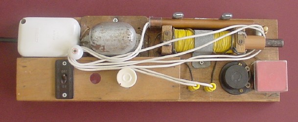
Here you see its present incarnation. It's had a bit of a refit since its
early days - not because it didn't work well; it did - but I wanted to add a
few features and make it more durable.
The handles ("electrodes" is a suitably spooky-sounding alternative term!
A short piece of tightly-fitting clear plastic tubing was placed over the
end of each handle to hold the wire steady and minimize possible damage to
the soldered joint in the event of the wire being pulled sideways or
otherwise stressed. The other end of each wire was soldered to a yellow
banana plug; these connect to yellow banana terminals on the wooden base.
The picture above shows the unit neatly packed up. The handles are stashed
behind the coil itself (yellow). They are held in place by two small
right-angle shelving brackets screwed to the base below the coil; each has a
short length of clear plastic tubing pushed over its vertical half, to hold
the handles gently but firmly in place. The large pearly bead, mounted on a
long screw which then passes through a distance piece made from part of an
old telescopic TV antenna and then into a hole drilled in the base, is there
simply as part of the anchoring system for the wires in this configuration.
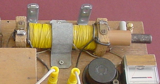
In this next picture, the handles and their wires are unpacked. Also, the
red cover at lower right has been removed to reveal a small meter
underneath:
Now for a description of the various components:
This project plugs into the mains, with its own transformer - the
silver-painted object at the rear.
To the left of the transformer is a white plastic junction box; you can see
the black mains flex entering this at the left. The active lead goes to the
switch. The neutral lead and a wire from the other side of the switch are
connected to the transformer primary. The transformer core and cover are
connected firmly to the earth lead.
The transformer itself has a 4V AC output. I seem to recall my Dad
describing it as a loudspeaker transformer, presumably from an old
mains-operated radio or similar.
The shocking coil was made pretty much according to Bulman's specifications.
It was wound onto a piece of grey plastic pipe about 12cm long, with an
inside diameter of 1.6cm. The ends were made from chip-board 1.4 cm thick
and 3.7cm square.
The primary - 50 turns of enamelled copper wire about 1mm in diameter - was
wound first. As I recall, this was covered with insulating tape. The ends of
the wire were brought out through holes drilled in the chip-board pieces.
The secondary was about 3,000 turns of enamelled wire about 0.3mm in
diameter. Each layer was insulated from the next by a layer of insulating
tape, and the whole thing covered with yellow insulating tape. The ends of
the coil are soldered to brass tags screwed to the tops of the chip-board
end-pieces. Short black wires connect these to the yellow banana terminals.
The core for the shocking coil is a solid iron rod 17.9cm long and 1.2cm in
diameter. The left-hand end is a snug fit in a short piece of copper pipe
3.6cm long and with an outside diameter of 1.6cm - just big enough to be,
itself, a snug fit in the plastic tube on which the coil was wound.
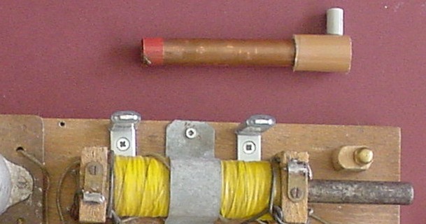
The way the iron core is fixed inside the coil allows a copper pipe, inside
diameter 1.2cm and outside diameter 1.5cm, to slide easily over the core and
inside the plastic tube. This pipe is 11.5cm long. Its right-hand end is
pushed tightly inside a 3.1cm-long piece of plastic tube equipped with a
handle made from the end of an old ball-point pen. This makes it easier to
slide the pipe in and out of the coil. (The purpose of the pipe will be
explained shortly.) Here is a close-up of the sliding pipe:
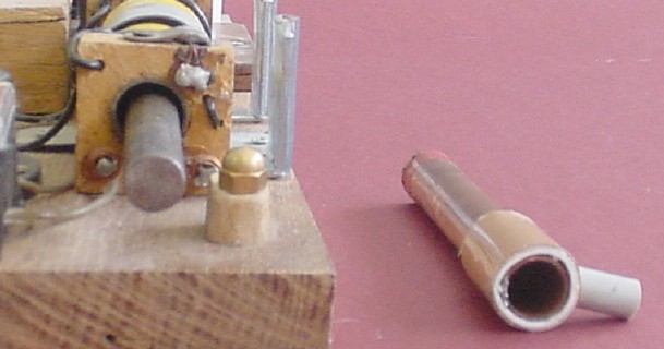
- and here is another view, also showing the end of the core so that you can
see how the sliding pipe will fit over it and inside the coil.
The small piece of red insulating tape on the left-hand end is there to
alert the user that the sliding pipe is almost completely out of the coil -
somewhat as retractable mains leads on vacuum cleaners have a bit of red
tape near the inner end to alert the user not to pull any more out.
(The little wooden pillar with the brass dome nut on top is just there to
prevent the pipe from sliding off, when the handle is pushed down next to
the dome nut.)
This picture shows the unit operating, with the sliding pipe pulled
partially out.
There are a couple of differences from Bulman's coil:
Firstly, his core was made made up from iron wires, twisted together and
reinforced with a surface layer of solder. Thus it was partially laminated;
the fact that the wires touched each other at various points along their
length, and also the presence of the solder, to some extent defeated the
ability of the partial-lamination to reduce eddy currents.
In my coil, there is no attempt to reduce eddy currents; using a solid iron
bar allows them to form readily. As it turns out, this is a good feature
(more on this later).
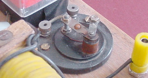
Secondly, Bulman arranged a traditional-type interrupter to be operated by
the magnetic field of the coil. Again, much as in my
ignition coil circuit
, an external interrupter was used. This time, it was a simple old-fashioned
round black buzzer. Here's a picture of this little classic with its cover
removed:
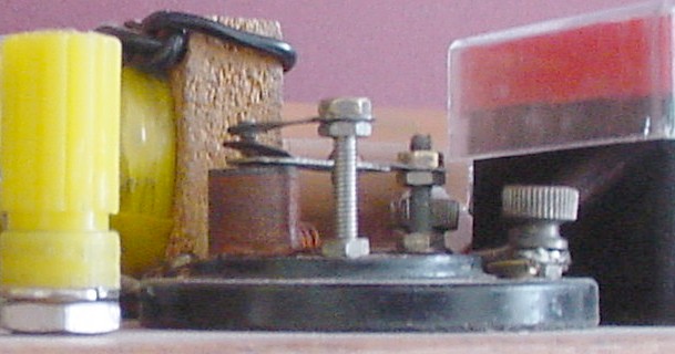
- and again, from a different point of view:
When I revamped this project, the buzzer needed some attention to get it
buzzing really well. This was a very ticklish procedure; a slight
adjustment of a contact can stop it working altogether! Fortunately, with
patience and perseverance, I was able to get it working quite efficiently,
at all settings of the rheostat (described next).
To the left of the yellow banana terminals is a small box, made from plywood
and open at the back, which houses the mains switch, a torch globe under a
transparent red cover, and a rheostat - a wire-wound predecessor to
the modern potentiometer, or variable resistor. It was probably made to have
a resistance of 40 ohms; I measured it at 38 ohms.
(If you'd like to read a bit more about rheostats, visit my
power supply
page, where you can read about how I very probably nearly ruined one.)
Note that neither Alfred P. Morgan nor A.D.Bulman used a rheostat, or
anything similar, in their shocking coil models. This was my Dad's
innovation, in our unit.
There are a few other components not yet discussed - most obviously, the
meter - but these represent additions and modifications made since 2002. In
essence, the project as described so far is pretty close to how it was
originally.
Here's the circuit diagram for the the unit as described so far:
Essentially, it's a small induction coil. The transients are generated by
the buzzer, which is quite simply in series with the primary.
There are some obvious differences from both the traditional induction coil
and my
ignition coil circuit
("Old Sparky"):
Firstly, the core is not laminated. It's a solid piece of iron; eddy
currents can build up in it quite readily. Moreover, the sliding copper pipe
serves to increase eddy currents, when it is pushed in.
Secondly, there is no capacitor across the "points" (i.e. the buzzer
contacts).
These two factors both tend to reduce the efficiency of the coil. However,
that's not a bad thing in this case! If it were too efficient, its
output may be dangerous.
Remember: the intention of this project is to provide a very
mild electric shock - just a "tingle". We're not playing "silly
buggers" here. Thus, if natural inefficiencies tend to "rein in" the output
power of the unit, so be it!
When operating the coil with the rheostat turned fully anticlockwise (i.e.
maximum resistance) and the sliding pipe pushed fully in, there is little if
any sensation. Depending on such factors as the dampness of the user's
hands, turning the rheostat up may bring a slight tingle. Now, in my middle
years and with quite dry skin, I find that there is hardly any sensation
even with the rheostat fully clockwise. (I always start with it turned down,
however, just in case!)
With the rheostat fully clockwise, and having over several seconds become
accustomed to the sensation (if any), I then very carefully start to pull
the sliding pipe out. When it's out to (say) three centimetres, I become
aware of a definite sensation, which increases as it is pulled out further.
I've had it pulled out all the way sometimes, for a few seconds at a time.
The sensation is then quite strong. It's important to be fully focused and
to monitor how one feels at any moment. Movement of the controls is to be
done slowly and carefully.
Yes, it is fun! Boys will be boys - even when they get to be quite
old boys.
Now: to a description of various modifications I made to the shocking coil
when I "did it up" in 2002. Refer to the following circuit diagram:
Firstly: the 6.1 ohm resistor.
This was an attempt to make the rheostat more "meaningful". The way it was
originally, you had to have it turned almost right up to get anything out of
the unit at all. I thought that by placing a smallish resistor in parallel
with the rheostat, I'd start to feel a tingle at a less extreme setting.
I had an old element from a bar-heater lying around. (I'm sure you've
realized by now that I've got lots of odd things "lying around".
I'm not quite sure now how I measured its resistance as 6.1 ohms. Certainly,
my old multimeter isn't accurate enough to let me measure it directly to
that degree of accuracy! I might have measured the length and resistance of
the entire element and then used proportions based on length to estimate it.
I can't remember - sorry!
Secondly: the meter, and associated components.
An old AIWA reel-to-reel tape recorder I had from the 1970's eventually
"packed it in". Various things started to go wrong; initially I had in mind
to try to fix it, but I became disheartened as I looked at the scale of the
exercise. Eventually, and sadly, the machine assumed the status of "parts".
Two of these parts were the original VU meters - simple little devices
without any markings other than to show when the amplifiers were "peaking
into the red". I decided it would be fun to try to include one of the meters
in my shocking coil project, to give a simple visual indication of - well,
some kind of "average primary current", I suppose! Basically, it's just
there to monitor the rheostat setting. So I wired it into the circuit as
shown above.
Again, we're talking small resistances. I may have used bits of nichrome
wire or something similar; they may be more bits from the old bar heater
element - I can't remember. Also, again, I'm not sure how I measured or
estimated their resistances. (The 4.7 ohm resistor may possibly have been a
commercial item.) Neither can I remember what sort of diodes I used, or why
I used two of them. When I added these features in 2002, I did have the
forethought to draw a circuit diagram and mark the values on it, but
neglected to write down any details regarding the physical nature of the
components used or how I determined their values. Silly me!
The important thing is that the way it is now, it gives a maximum deflection
- just before "peaking into the red" - with the rheostat fully clockwise.
(With it fully anticlockwise, it gives a very small but definite indication
that there is actually some current flowing in the primary circuit, even if
it's too small to produce any sensation from transients in the secondary.)
I mounted the meter into a section cut from a plastic soup-cube box, along
with all these bits'n'pieces, and covered the sides with black gaffer tape
to hold everything together. I'm loath to disturb it, so I'm afraid you'll
probably have to get through your life somehow without knowing exactly
what's inside the box. Again, sorry! (If it ever stops working properly, so
that I have to investigate, I'll update this page with the details.)
The cover from the meter was made from the red lid of the afore-mentioned
soup-cube box, and part of a similar somewhat larger box.
If you've come to this page by way of my menu system, you will have already
seen the following graphic:
- which is an idealized representation of switch-on and switch-off
transients in an electromagnet. In an induction coil such as my shocking
coil, the primary coil plays the part of the electromagnet winding; and
these transients are magnified (in voltage terms) in the secondary coil.
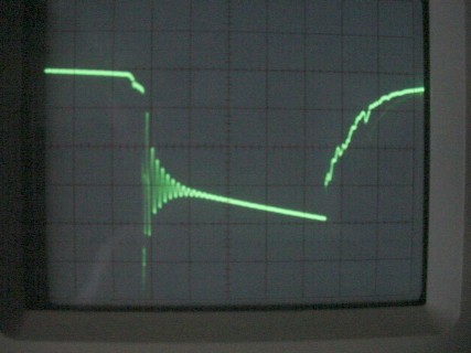
Following is a photograph of my oscilloscope's screen showing these effects
in the primary circuit of the shocking coil. (I connected the oscilloscope
probes across the buzzer terminals to obtain this.) The oscilloscope
triggers on the higher-voltage switch-off transient, so that this occurs
first in the trace followed by the switch-on transient:
The basic structures of the transients are clearly visible, if a bit
"ratty". In real life, things are rarely as clear-cut as theory says they
should be.
About three-quarters of the way up the switch-on transient, near the
right-hand side of the trace, there is a small but quite clearly visible
downward-pointing spike. I suspect that this is where the buzzer's contacts
open and a small spark occurs. Then, presumably, any "stray capacitance" in
the circuit (probably due largely to the meter) behaves in much the same way
as the capacitor in a more standard induction coil circuit (for example, my
"Old Sparky"
ignition coil circuit
),
allowing current to flow into the primary for just a bit longer. But I'm not
sure! If you have any thoughts on this, you might like to
contact me
and share them.
By the way: it should be noted that oscilloscopes show voltage, not
current, on the vertical axis - whereas the graphic above shows
current. Thus, although the trace is obviously very similar to the
graphic and closely related to the effects depicted therein, "the devil is
in the detail".
Actually, the above photograph is itself a somewhat idealized picture; in
reality, the trace was jumping around in a quite lively manner, because the
buzzer is far from a "clean" signal source. I was just lucky that the camera
happened to pick up a good image in the split-second when the picture was
taken.
Now, remember that this project uses an AC power supply. This is unusual for
an induction coil; historically, there was no such thing as AC when
induction coils were first developed in the 1800's, and batteries (DC) were
used to power them.
Hence we'd expect things to be a bit different from the traditional
situation with this circuit. Indeed, it turns out that there is a 50Hz AC
component in both the primary and secondary currents, in addition to the
contribution from the transients. The question arises: just how much
50Hz AC is present?
It's an important question. Mains current itself is notoriously dangerous;
part of the danger is due to the fact that its rather low frequency (50Hz in
Australia and some other countries; 60Hz elsewhere) can interfere with the
nervous system and cause ventricular fibrillation. Even fairly low voltages
at these frequencies may be dangerous under certain conditions. (See, for
example, the comments about frequency in
this page
, which is basically about Tesla coils but which also contains general
safety information relevant here.)
The downward slope of the trace after the switch-off transient is due to the
fact that the transients are superimposed onto 50Hz AC from the mains
transformer; and for the instant when the oscilloscope triggered, the
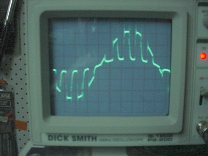
sinewave voltage was decreasing. By re-setting the time-base to give a
horizontal scale of 2 milliseconds per division - and thus a total
horizontal scan of 20 milliseconds, corresponding to a frequency of 50Hz - I
obtained the following trace:
- in which the sinusoidal nature of the mains "fundamental" can be clearly
seen. (The first two transients - the left-most ones - correspond to those
on the first photograph, which is thus a "blow-up" of that part of the
second - although the aspect ratio has been changed.)
In this image, the vertical scale is 0.2 volt per division, so that the
"external" sine-wave has an amplitude of about 0.6 volt and the "internal"
one has an amplitude of 0.1 volt. Pretty small; but to make sure, we really
need to see how much 50Hz signal is present in the secondary - because
that's ultimately what the user is hanging onto!
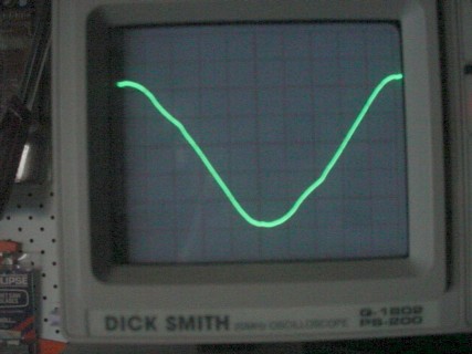
To find out, I shorted the buzzer-meter series combination, so that the
coil operates essentially as an ordinary AC transformer. With the rheostat
turned fully up and the sliding tube removed entirely from the core (to
maximize the output), and the probes connected to the coil's handles, I
obtained this trace:
This time, the vertical scale is one volt per division, so that the
amplitude is about 2.6 volts - very small. Clearly, the solid iron core is
absorbing most of the 50HzAC energy in the form of eddy currents,
effectively eliminating the danger.
I haven't attempted any oscilloscope investigation with my
ignition coil circuit
("Old Sparky"), because I don't want to risk wrecking my oscilloscope - and
possibly putting 20-odd thousand volts across any connection to the house
wiring - if something goes wrong!
I know it's possible to do it safely, but I'm not game to try it. If you'd
like to see an example, visit
Kurt Schraner's website
to see his big spooky, sparky induction coil and several oscilloscope
traces of it working, with considerable in-depth analysis.
PLEASE READ THIS
In closing, I stress that this page is not an attempt to encourage
macho tough-guy behaviour by irresponsible people. You should always
be wary with any electricity capable of being felt. In particular, if you
ever experience such a sensation from a commercial electrical appliance, it
needs urgent attention. If the same happens with anything associated
with house-wiring and/or plumbing fixtures, call a qualified electrician
immediately and get it sorted out before something tragic occurs.
In the final analysis, this project is educational in nature. If you
experience a safe, controlled, very small electric shock, you'll know what
it feels like without getting hurt - and you will thus be aware of danger if
you experience anything like it in an inappropriate situation.
My home page
Preliminaries (Copyright, Safety)
Shocking ("medical") coil (ca. 1967)

 As long as
you take suitable warning from the incident, I don't mind - it's worth it!
As long as
you take suitable warning from the incident, I don't mind - it's worth it!
 ) are two pieces of 1.2cm diameter copper pipe, each
15cm in length and with a small hole drilled near one end. Two 95cm lengths
of white insulated wire were prepared, one for each handle. The insulation
was stripped from their ends; one bare end of each wire was passed through
the hole in one of the handles from the outside, and then soldered to the
inside.
) are two pieces of 1.2cm diameter copper pipe, each
15cm in length and with a small hole drilled near one end. Two 95cm lengths
of white insulated wire were prepared, one for each handle. The insulation
was stripped from their ends; one bare end of each wire was passed through
the hole in one of the handles from the outside, and then soldered to the
inside.


 ) Using crocodile clips to place part of the element
in circuit, I experimented to find something that seemed reasonable; then I
cut the required short length and wired it in, near to the rheostat. So it's
concealed inside the plywood box.
) Using crocodile clips to place part of the element
in circuit, I experimented to find something that seemed reasonable; then I
cut the required short length and wired it in, near to the rheostat. So it's
concealed inside the plywood box.
![]()
(Shades of our Sydney Harbour Bridge...?
)
 Return to Induction coil projects sub-sub-menu