
This page added on Friday, 10th July 2009
This photograph has already appeared twice before in this website: in my
...and so this is Christmas...
page, posted in late December 2008; and in my weirdly-named
2
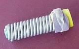
The little gadget it depicts is my first attempt to make a motor of the
type described by John Bedini (JB), a US electronics engineer who claims to
have been building such things since 1984.
If you've seen my
... ZPE "contenders"...
page, you may recall that I first became aware of JB's work last year
(2008), and started building motors along similar lines in early September.
Click
here
to visit a web-page which gives an introduction to the topic, including a
bit of history and some technical details - enough to enable readers to
attempt to build their own simple monopole motors.
CAUTION:
There is some risk associated with motors of this type. As JB mentions in
his own writings, it may be possible to receive an electric shock from
them; however, perhaps more significantly, there is a danger of physical
disintegration! These motors can spin very fast, and if they're not
well-built, it's possible that one or more of the magnets attached to the
rotor may go flying off in unpredictable directions. [This hasn't happened
with the motor described in this page, but it did happen with
my second Bedini motor
- and I consider myself very lucky that my eyes (especially my one "good"
eye) weren't in the "firing line" at the time.] Or, of course, the whole
rotor may become detached and go spinning out of control if the motor
itself is not sufficiently sturdily built. So, if you build a motor of
this type, be careful; having drawn attention to the possible dangers, I
cannot and will not accept any responsibility if something goes wrong.
As mentioned in the web-page whose URL has just been given, JB asks people
to follow his method closely when constructing their first motor, so as to
ensure success - and only then to start "playing around" with some of its
features in an attempt to improve its performance.
This presented difficulties for me. Experience has shown that rectangular
ceramic magnets of the exact type he specifies - quite large, with a
screw-hole in the centre - are not available in Australia (or, at least, I
haven't been able to find any). Also, obtaining winding wire of exactly the
gauges he specifies is not quite straightforward (more details shortly).
JB used mild steel welding rods cut to size and inserted into the coil as
its core. I suppose I could have cut some large iron nails to size and
done much the same with them; but just for fun I thought I'd try something
quite different (ever the rebel!). I happened to have lying around a
broken piece of ferrite rod of just the right length, and an old spring of
the type that is used to make gates swing shut when released. Read on to
see how I utilized these.
So: with what I had on hand, I did the best I could; and the little machine
I constructed following JB's instructions fairly closely does work
quite well - well enough, certainly, to warrant further research.
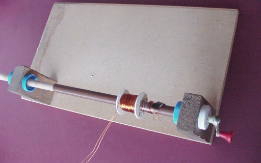
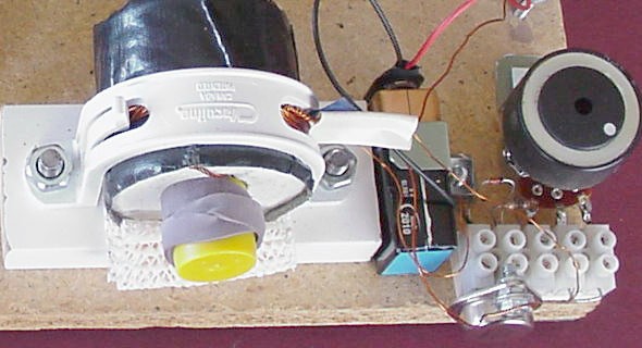
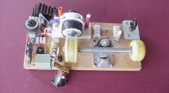
It's a very simple device. Its components are as follows:
(A small compass is shown here too.)
I put a strip of the sticky stuff on the wheel, and pressed the magnets into
it, equally spaced (to the best of my ability). I used the compass to ensure
that they were all mounted with the same pole facing outwards, i.e. all
attracting the "north pole" of the compass. Then I eased the plastic ring
over the wheel to hold everything in place.
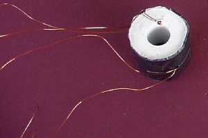
This is a bifilar coil. Two strands are wound simultaneously, keeping them
as closely together as possible, rather than with one winding over the
other.
It's worth saying a bit about bifilar coils at this point. Click
here
to see US Patent number 512340, "Coil for Electro Magnets", issued to
Nikola Tesla in 1894. (Like anything written in Tesla's elegant, poetic
style, it's well worth a read.) Then click
here
to see a Wikipedia article about bifilar coils.
These are a fundamental feature of JB's monopole motors. In our present
case, the two windings are wire of different thicknesses. JB specifies #23
and #26 gauge wire (the first is thicker than the second).
There is some room for confusion here. Visit
this
Wikipedia page to gain some understanding of how the American Wire Gauge
(AWG) system works. AWG 23 wire is of such a thickness that a winding of
17.4 turns wound onto a rod will be 1cm in length, while for AWG 26 wire,
the corresponding number of turns is 24.7. [Note that the ratio is about
1.42, i.e. approximately the square root of two - which, as that page
implies, should be the case for a gauge difference of 3 (it's a
logarithmic scale).]
When I went to buy some winding wire last year, for this and other projects
I had in mind, I found (again, as that Wikipedia page asserts) that in
Australia (and other countries) it's common to refer to the actual
size of the wire. I bought wire of two different diameters, not being
entirely sure that I was getting exactly what JB specifies. When I did my
own "turns per centimetre" tests later, the figures I obtained were 20 and 14
respectively. Again, the ratio is approximately the square root of two - but
both wires are apparently slightly thicker than those specified. (I hope you
haven't found all that too confusing!
Actually, there is another common wire gauge system known as
"Standard Wire Gauge", or SWG.
Here's
a web-page which has a comparison of SWG and AWG for different gauge
numbers; it's apparent from this that wire of a particular SWG gauge
is a bit thicker than wire of the corresponding AWG gauge - so that's
probably the scale that was used when I bought my wire. Life, simple, it
ain't...
Anyway, I carefully wound 600 turns (give or take a few) of the two
wires together, which filled up the spool quite well. (JB specifies 450 to
800 turns, so presumably I'm in the "ball park" there!) Then I wrapped it up
in black gaffer tape to give the result you see above.
I didn't try to wind it "by hand", holding the spool in one hand and winding
the wire on with the other. I took the trouble to make myself a "winding
jig" with a crank handle (part of an old window-opener - guess where I
bought it?
(Even then, things can still go wrong! In the next page - about my
second monopole motor - I'll have a horror story to tell...
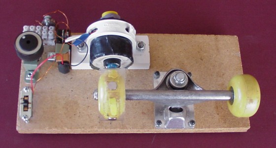
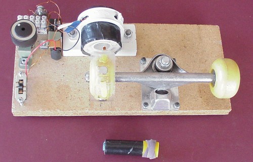
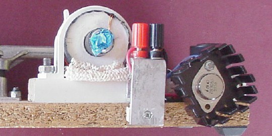
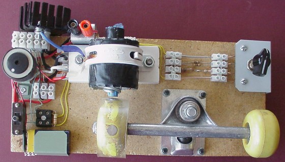
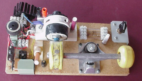
I used a piece of chipboard, 29 × 13 × 1.8cm, as the base, and mounted
everything as you see in the picture at the top of this page. I used a small
piece of timber as a platform to raise the coil to the same height as the
wheel, and an old plastic pipe clamp to hold the coil in place. (Guess
where...)
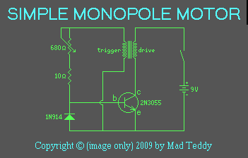
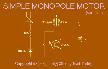
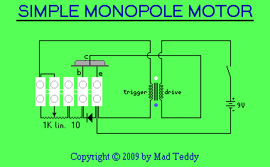
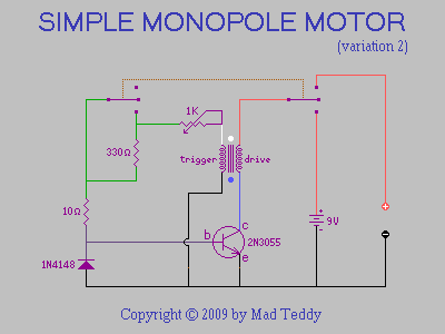
Now: to the electronics. Just a handful of components, basically!
There's a diode, 1N914. (I've used a 1N4148, which is pretty much
equivalent.)
The only other components: a 9-volt battery (and connector clip), a
switch, a 10-ohm resistor, and a 680-ohm linear potentiometer (variable
resistor). [You can't seem to get those here, so I've used the next-best
thing: a 1,000-ohm (1K) lin. pot., which works fine.]
If you've had a look at the "introductory" page whose link appears above,
you've probably seen a circuit diagram for the motor. The following diagram
is my own version, which I find easier to follow - because over time I've
become used to thinking of transistors drawn in that configuration, with
the base at the left, as is common in amplifier-type circuits (even though
the transistor here is being used not as an amplifier, but as a
switch):
- and here's another one with my diode and potentiometer substitutions:
Notice the blue and white dots at either end of the coil. These correspond
to pieces of plastic tape of those two colours that I placed on the ends of
the windings, to make them easy to identify at a glance. (You can see these
pieces of tape quite clearly in the photograph at the top of the page, and
in more photos further down.)
As you can see, it really is a very simple circuit. The right-hand half -
the "drive circuit" - consists of the "drive coil" (the thicker winding),
the collector-emitter path through the transistor, and the battery (and the
switch, of course). The left-hand half - the "trigger circuit" - comprises
the "trigger coil" (the thinner winding), the diode, and the
resistor/potentiometer series combination. The two halves are linked by a
common connection to battery negative; a connection from the diode-resistor
junction to the transistor's base; - and whatever inductive effects take
place between the two coil windings.
What's not shown in those diagrams is the wheel itself, with its four
magnets. This is positioned next to one end of the coil so that it can spin
freely with the magnets missing the core by a short distance - a couple of
millimetres, perhaps (I've found that this is not critical).
It's important to make sure that when the drive coil is conducting, the end
of the core past which the magnets will travel has the same polarity as the
outer poles of the magnets on the wheel, so that they are repelled by the
coil. If not, it's necessary either to reverse all the wheel's
magnets, or to turn the coil around end-for-end, or to reverse
the connections to the coil (both windings!). (To test this, we can
simply short the transistor's collector to its emitter, and then switch on
for just long enough to be sure everything is OK.) I used my little compass
to make sure the coil's "front end" polarity matched the outward-facing
poles of the wheel magnets (i.e. it attracted the "north pole" of the
compass).
It doesn't matter whether they're all north poles or all south poles. JB
uses the term "North Pole Motor" in his diagrams, so presumably all the
relevant poles are north poles - which would then attract the "south pole"
of the compass. Of course, this can be confusing; if your scientific
education includes such terms as "north-seeking pole" with reference to
compass needles, so that you're muddle-headed about what's really
going on, you might well end up with a "South Pole Motor" instead - which
is, apparently, what I've done!
Just by the way: I've used the terms "drive circuit" and "drive coil"
here. In some writings about these monopole motors - or "Bedini motors", as
they are also called - the terms "power circuit" and "power coil" are used
instead. (The word "trigger" for the thin-wire-coil part of the circuit
seems to have become standard.)
I mounted all the electronic components - transistor, diode, resistor, and
even the potentiometer - on a five-terminal piece cut from a small terminal
block (these come as standard with 12 terminals). I had to solder short wire
links to the potentiometer's connectors to make them reach far enough. I
mounted the terminal block on a small piece of timber to allow a small gap
between the potentiometer and the base, and secured the potentiometer by a
small zigzag strip of sheet iron screwed to the base.
Here is a version of the circuit showing the terminal block connections:
Diodes have a bar near to one end, a different colour from that of the
main body. This end is the cathode (the left-hand end, in the
diagram above). The other end (the triangular "arrow-shaped" part, in the
diagram) is the anode.
It's important to connect diodes the right way around. If you do it wrong,
a circuit will usually not work - or you may even damage the diode. If
you're guessing, you've got a 50% chance of being right! So it's a quick
learning curve - if you put a diode in the wrong way around and thus wreck
it, you'll just have to get another one, won't you?
If you'd like to read more about diodes,
this page
gives a good introduction. Alternatively, if you'd like a much more
in-depth treatment, click
here
to see the Wikipedia article. [Note that "ordinary" diodes and
light-emitting diodes (LEDs) are constructed rather differently; LED's
need to be handled carefully also.]
The battery was (originally) positioned to the left of the coil's platform
and secured in place with another small sheet-iron zigzag strip. (Later, I
relocated it to make room for something else, as will be explained
shortly.) The switch was placed at the left-front corner of the base.
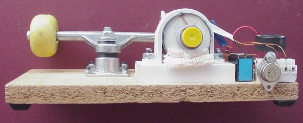
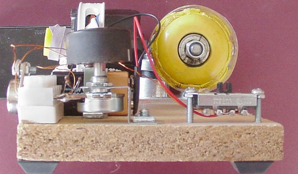
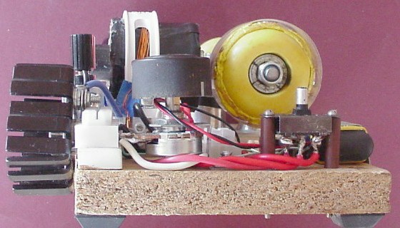
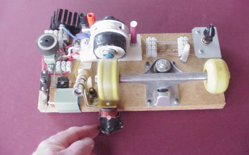
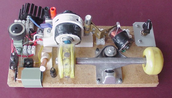
Here are some more photos of the motor:
Generally, the motor is best started with the potentiometer turned right
"down", i.e. anticlockwise, so that its resistance is down to zero. When
you switch on, nothing at least appears to happen at first (I'll
have more to say about this later). To get it running, you give the wheel
a firm "swipe" with your hand. Provided you impart a good enough initial
spin, it will continue to rotate - and even pick up speed over a few
seconds.
Once the motor is running smoothly, the potentiometer can be turned up
slowly - and the motor's speed will increase further, up to an optimal
"sweet spot" setting of the pot. beyond which the wheel will begin to slow
down (and may even stall completely, depending on a number of factors
including the condition of the battery).
I got quite a "buzz" out of seeing this working for the first time! Until
then, I wasn't really sure whether it was all a hoax. It's not -
these motors do work, surprisingly well. With a fresh battery (and
even with one that's starting to show its age a bit), the wheel will rotate
quite happily at over 50 revolutions per second, or 3,000 revs per minute!
Click
here
to see a 15-second, 1.3Mb mpeg movie of the machine running. While
valiantly trying to hold the camera steady and operate it with my right
hand, I start the motor with my left and fiddle with the potentiometer to
find the "sweet spot". Toward the end, you can quite clearly hear the
motor revving up.
So - how does it work?
I'll be honest - I'm still on a learning curve about this. Here's a very
simple "explanation":
Initially, the transistor is off (i.e. there is a very high resistance
between its collector and emitter). There is no battery current flowing
through it (or, at the most, only a tiny leakage current, which is
insignificant) because there is no voltage on the transistor's base. So
there is essentially no current in the coil, and thus no magnetic field
produced by it.
When the wheel is set spinning, a magnet approaches the coil (attracted to
some extent by the core, just as any magnet is attracted to any
unmagnetized piece of ferromagnetic material). As it approaches, the
principle discovered by Michael Faraday kicks in: a voltage is induced
across each of the coil's windings. As far as the drive coil is concerned,
any resulting current is still insignificant, because the transistor is
(initially) still off, so nothing really happens there. However, the
current in the trigger coil resulting from its induced voltage is
enough to put a positive voltage on the transistor's base relative to its
emitter (by the "potential divider" action of the diode and the
resistor/potentiometer combination), and the transistor then switches on -
i.e. the resistance from collector to emitter drops dramatically.
This allows the battery to send a substantial current through the drive
coil, which thus becomes an electromagnet. Because of the way the circuit is
wired, the direction of the magnetic field is opposite to that of the
nearby permanent magnet, which is thus repelled - quite forcefully.
With the magnet moving away, the trigger circuit "shuts down", and the
transistor switches off - so that the drive coil is no longer an
electromagnet. The wheel continues to spin (by flywheel action); another
magnet comes along - and the process repeats. Thus, we have a motor!
I'll admit that I don't fully understand how the trigger circuit works.
Quite "clearly" (says he, with his fingers crossed behind his back), there
is a "potential divider" action which places enough positive voltage on the
base to switch the transistor on as the magnet approaches; and the diode
(fingers on both hands crossed now!) acts to block current in the
trigger circuit as the magnet moves away, to make absolutely sure that the
transistor is really off at that time. (If you know better, and can
enlighten me, please
contact me
and put me straight, so that I can improve on what I've written here.)
But that really is only a very simple explanation. If that's all
there is to it, it's still just a rather odd kind of motor, with the battery
providing all the power. However, JB's assertion is that this is not
the case. In fact, he claims that the motor can be modified to charge
a second battery faster than the "drive" battery runs down! - and
that's what makes these motors exciting.
The motor described here is really only a "proof of concept" device, just
to show that it really does "go". It's basically similar to the motor
built in 2000 by a schoolgirl of JB's acquaintance, who wanted to enter a
project in a school science fair. With his help and advice, she did indeed
build quite an impressive little project, which won the science fair
competition handsomely!
Visit
this web-page
to read the full story, and more information about this entire phenomenon
besides. The part about the schoolgirl and her science fair project begins
about three-fifths of the way down.
But there's a lot more to say about the matter. It has to do with
high-voltage transients, and (I firmly believe) it has to do with Werner
Heisenberg's assertion that we could
"utilize magnetism as an energy-source".
It seems that the fact that the two coils are wound onto the same core -
and in a bifilar manner to boot, thus dramatically increasing the coil's
capacity to store energy - is the key to any attempt to tap into ZPE with
this system. As you'll see shortly from photographs of my oscilloscope
screen, the waveform produced by the motor includes some quite dramatic
relatively-high-voltage transients ("spikes"), which seem to be a hallmark
of any attempts (that I've seen, anyway!) to harness ZPE. I gather that
this, in combination with the action of the magnets, is what JB claims is
responsible for making the system function as a "radiant energy" device.
You may find
this page
- a discussion forum - interesting and helpful with regard to
understanding how and why bifilar coils are used in Bedini motors.
Early experiments I conducted with the motor involved running it from small
9V batteries of different "vintages" - some almost brand new, and some
pretty much "past it" in everyday practical terms. (You know how I can't
bear to throw things away, don't you?
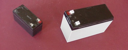
I'd bought a large-ish 7 amp-hour gel battery (right, above) some years
previously, and hardly used it. It still registered a healthy 12V+
"open-circuit" voltage. Now, I bought a smaller, 3 amp-hour gel battery
(left, above; also 12V), on the principle that I was hoping to ultimately
produce a two-battery system with one battery running the motor, and the
other charging, hopefully at a faster rate than the drive battery was
being run down - an "over-unity" system. (That's still my ultimate hope;
but I'm not there yet.)
So, having these various batteries on hand, I tried them all as power
sources for my little masterpiece.
With a fresh 9V battery, it runs very well, quite a bit faster than 3,000
rpm (revs per minute). With an older 9V battery down to (say) 7.5V, it
still goes quite well, but struggles to reach that speed. Eventually, with
one of these batteries down to about 7V, it won't even start. (There has
to be some "juice" to operate the trigger coil, after all!)
When I started experimenting with gel batteries, however, I noticed odd
things happening. In certain instances, when I switched on, even
before I started the wheel spinning, something in the motor
began to "sing" - a quite audible "whine", the pitch of which could be
varied by adjusting the potentiometer.
It was difficult to tell precisely where this oscillation was coming from.
It may have been the coil; it may have been the transistor (which seemed
the likeliest candidate to me) - I really couldn't tell for sure. Since
then, I've seen some websites which raise the same issue; even now I'm
still not sure what to make of it.
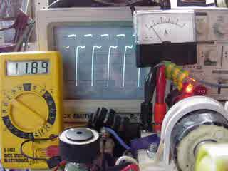
I hooked the motor up to my oscillosope (with the probe clips attached to
either end of the drive coil) and took some 15-second (1.3Mb) mpeg movies,
with both old and new 9V batteries and also both gel batteries (the small
one gave rise to the strongest oscillation). I placed the motor in front
of the oscilloscope, so that the trace appears in the movies along with
the motor itself.
To see the movie, click
here. (Note that it
took two "swipes" to start the motor!)
As the speed of the motor increases, the waveforms shrink in toward the
left. (In these movies, the oscilloscope beam's sweep is set to two
milliseconds per division. There are 10 divisions across the screen, which
thus represents 20 milliseconds (so that there are 50 full-screen
left-to-right sweeps per second).
In the final frame (above), there are about five divisions - or 10
milliseconds - between spikes. Since there are four spikes per wheel
revolution, the wheel rotates once every 40 milliseconds, corresponding to
a speed of 1000/40 = 25 revolutions per second, or 60×25 = 1,500 rpm. (On
the vertical scale, each division corresponds to one volt, indicating a
voltage range - the difference between the highest and lowest voltages
visible - of about 5.5 volts.)
The second of these movies features a newer 9V battery (click
here
to see it.) Actually, there's little if any increase in speed; but the
voltage range is slightly larger. However, one feature that is new
here is the appearance, near the beginning and at the end, of a small
"glitch" about halfway down the "spike".
The third movie (click
here)
has the motor running on the large gel battery. It gets up to a slightly
higher speed. The "glitches" from the previous movie are in evidence
again at certain times; these now appear as small "secondary spikes".
In the fourth movie in this set (click
here),
the small gel battery is used. Again, a slight increase in speed, and a
larger voltage difference - and, again, "secondary spikes" are quite
evident. This time, these appear to be more complicated - considerably
larger, and with what appears to be complex phenomena occurring
within them. Note that I had the pot. turned right up toward the
end, and even then it's by no means certain that the motor might not have
gone even faster if I'd had some extra resistance in reserve; it was this
kind of thing that later led me to add extra circuitry to make this
possible, as will be described shortly.
Running the motor with the small gel battery quite often caused
oscillations. Click
here
to see the fifth and final movie in this set, in which you can clearly
hear an oscillation - and see a waveform on the screen - even when the
motor is not spinning. In fact, attempts to get it to spin were
unsuccessful on this occasion (note, however, that the potentiometer was
not at its minimum setting, which can make it more difficult for the motor
to start). Toward the end, you can see me slowly rotating the wheel back
and forth through about a quarter of a turn, and hear the pitch of the
oscillation change slightly in response. (It sounds to me like a dazed
mosquito might sound!) Clearly, things are not quite as simple as they
seem, even for such a simple circuit.
Note that, in this movie, the spikes are "upside-down" by comparison with
the previous ones, presumably because I connected the probe clips the
other way around - although I didn't document the fact at the time. It's
even possible that I had the 'scope connected across the trigger coil
rather than the drive coil (as I did on some occasions), without bothering
to make a note of the fact. (Sloppy...
Over time, I managed to get improved performance from the motor. (Doing
something as simple as squirting some spray silicone lubricant into the
wheel's bearing could make quite a difference.) Eventually, by "tinkering",
I persuaded it to run at about 3,000 rpm on a fairly regular basis. (I
even had it running at 4,000 rpm for a brief period!)
Eventually, the magnets began to work loose, probably because the
centrifugal effect of them pressing against the inside of the plastic ring
during operation had stretched the ring slightly. I had to introduce some
more of that sticky stuff to tighten everything up. Later, it all worked
loose again; I eventually introduced quite a lot more sticky stuff,
as you'll see in later pictures. This, of course, had the effect of making
the wheel more massive and thus increasing its
rotational inertia,
which means that the motor's top speed - with a healthy 9V battery - is
now slightly less than before, but still well over 3,000 rpm.
You may have noticed from those movies that, with the more powerful gel
batteries, it's possible to have the motor running at quite "high"
settings of the potentiometer (i.e. set to higher resistance settings). In
fact, when the gel batteries were new, on some occasions it appeared that
the "sweet spot" had not yet been reached even with the potentiometer
turned right up (to its maximum 1K resistance), suggesting that a higher
series resistance may be needed. (This appears to be the case in one of
the mpeg movies presented above in which the small gel battery was used,
as already mentioned.)
I also noticed that, under certain conditions, with the potentiometer
resistance at a low setting, the transistor sometimes became quite
hot, as did the 10-ohm series resistor. It occurred to me that a bigger
series resistor might be a good idea, not only for the reasons already
given, but also to protect the potentiometer (which can be damaged quite
easily by high currents), as well as the transistor. Eventually, I added
some features to the machine in an attempt to deal with these matters.
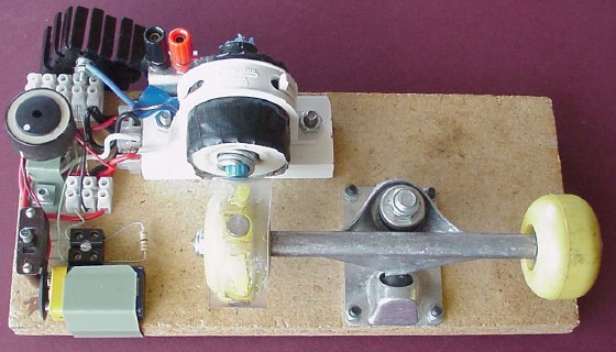
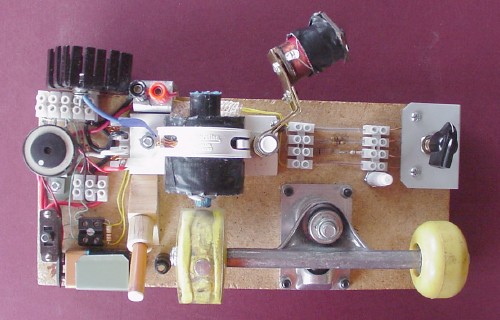
As a first step, I added a heatsink to the transistor. (The transistor's
case is known as a TO-3, and there's a heatsink specially made to suit it
- a fairly large piece of metal with cooling fins.)
Secondly, I added some extra circuitry. I replaced the original switch
(which wasn't really the best possible choice for the application) with a
double-pole, double-throw switch, wired in such a way as to allow me to
still run the motor from a 9V battery with the original 10-ohm resistor
(which, it seems, is always adequate with a 9V battery), or from some
other power supply with a higher series resistance. To facilitate such an
external power source, I installed a pair of banana terminals (whereas
before I'd been simply attaching the gel batteries with clip-leads to
appropriate points in the circuit - quite scrappy).
The extra circuitry was initially just a 330-ohm resistor, which you see
at lower left connected into a black two-terminal block (which, if my memory
serves me correctly, I'd found lurking among my Dad's old things
Notice that there's now also a terminal block attached to the left-hand
end of the coil's platform. This is to secure the ends of the winding
wire, which was previously connected in a rather messy "loopy" way to
other points in the circuit. (It's a good idea to do this, because
enamelled winding wire is somewhat brittle and prone to break easily at
a connection point if not secured.) Of course, this means that I've had to
relocate the battery, which is now at the front of the base, secured by a
sheet-iron clip.
The switch has a "centre-off" position. With it pulled toward you,
the motor runs from the 9V battery, and the 330-ohm resistor is shorted
out. With the switch pushed away from you, that resistor is in the
circuit between the pot. and the 10-ohm resistor, effectively making the
series resistance 340 ohms. Then the motor runs from whatever DC power
supply is connected to the banana terminals.
Here's a view from behind, which clearly shows the heatsink and banana
terminals:
(You can also see the "untidy" end of the core with its cap and rubber
band removed! Later, I trimmed some of the excess pale blue plastic away
with a pair of scissors.)
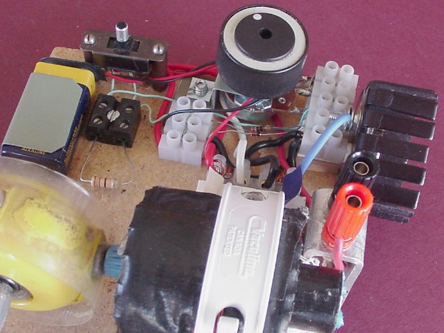
The next photo is of the left-hand end of the revamped motor, showing the
switch with its power connections. The wires are all red, in keeping with
the "red for positive" principle. (Similarly, all the "negative"
connections are black.)
The following photos were taken looking into the circuitry of the motor
from two different angles, in an attempt to clarify the details. (You can
click on them to see 640×480 versions.)
You can see the diode - brownish-red, with a black band near the
right-hand end - quite clearly in these photos, right next to the 10-ohm
resistor. The diode's cathode (the black-band end) and the 10-ohm resistor
are connected together via the terminal block connector into which the
transistor's base is connected from behind.
It may seem that the motor is quite a lot more complicated than before -
but really, it's the same circuit tidied up a bit and with a few more
options.
Here's the circuit diagram modified to show the new features:
This time, I've colour-coded the lines representing wires to match the
actual wire insulation colours in the motor itself, as an aid (hopefully!)
to following what's going on from the photographs.
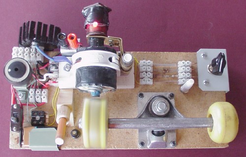
I did introduce a further modification to the circuit, which -
again - looks complicated, but isn't really. It's simply a resistor
network with a four-position rotary selector switch, which allows me to
vary the extra series resistance described above by from zero to the full
330 ohms, basically to add some extra flexibility with different power
supplies. (As before - with just the 330-ohm resistor - it has absolutely
no effect on the motor when it's running from its on-board 9V battery, as
the network is shorted out along with the 300-ohm resistor, with which it
is in parallel.)
You can see a pair of yellow wires - which run behind the coil's platform
- by which the new resistor network is connected across the 300-ohm
resistor.
The extra series resistance can now take the values 330 ohms (with the
rotary switch at its left-most position), 95 ohms, 22 ohms, and 0 ohms
(when at the right-most position). In the photo above, it's at the 22-ohm
position, which I've found by experience to be perhaps the most useful
setting. (Note that the 10-ohm resistor - the absolute minimum required -
remains in-circuit at all times. Thus the possible values for the
full series resistance are 340, 105, 32, and 10 ohms,
respectively.)
If you'd like to see the full details of this network, click
here;
if you'd rather not, it won't impede your understanding of the motor in
any way.
If you've visited
this web-page
(whose link was provided earlier) which tells the story of how a
10-year-old girl won a school science fair competition with a motor of
this type in 2000), you've probably read how her father positioned an
electromagnet connected to a light-emitting diode near the wheel to act as
a simple output device.
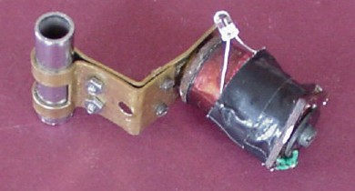
I've done something similar. An old electromagnet which once saw service
as one of two smoothing chokes in a DC power-pack (or "battery
eliminator") my Dad built in the early 1970's for my first transistor
radio, has now been resurrected and given something interesting to do!
I've soldered a LED to the ends of the coil and wrapped some gaffer tape
around the connections to protect them.
That LED is an 8,000 mcd "High Intensity Super Bright Sunset Red LED" -
very bright indeed. (The leaflet that came with it carries a warning: "Do
not stare into light".)
With the motor running, if I hold the electromagnet with one end near the
wheel's rim - so that the magnets move past the electromagnet - the LED
does indeed glow. This has the effect of slowing the motor down, to the
point where it will actually stall if it's being run from an old battery.
I've also found that the LED glows if I hold the electromagnet with its
end behind the motor's coil. Interestingly, in this case, it seems to have
little or no noticeable effect on the motor's performance.
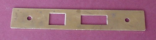
To facilitate the use of the electromagnet, I made a bracket for it from
an old brass door-lock mortise plate puchased for a few cents from
"you-know-where":
I carefully bent it into a specially-planned shape, clamped it to a short
piece of silver-painted copper pipe (left over from a previous project)
with some small nuts and bolts, and bolted it to the electromagnet, as
shown at left.
I installed two small pillars made from plastic crayon barrels onto the
base. One of them (maroon) is immediately to the right of the coil (I
replaced the short bolt with a longer one to hold it, and simply screwed
the crayon barrel on so that it cut its own thread). The other (light
brown) is to the left of the wheel, and angled pointing toward the
project's front edge at 45 degrees. (I cut a small piece of timber into an
isosceles right-triangular shape, secured it to the base by a couple of
small screws, and simply pushed the crayon barrel into a hole drilled to
make it a snug fit. A distance piece, made from a short piece of dowel
carefully drilled and reamed using a round file, was then placed onto this
pillar).
In addition, I installed the cap (white) from one of the crayons near the
left-front corner of the rotary switch's support, in a similar manner to
the maroon pillar; also a short black pillar (using a short brass bolt),
part of yet another crayon barrel (black, this time), closer to the wheel
than the sloping light brown pillar.
The electromagnet assembly can be placed onto the maroon pillar thus:
- from where it can be pushed to the left so that the the electromagnet is
directly behind the coil. With the motor running, the LED glows.
(In fact, the LED glows quite brightly even when the electromagnet is not
swung directly behind the coil, even - dimly - when it's still some
distance from the coil's end, about three centimetres in some cases, and
at a considerable angle to it!)
I've noticed that with the electromagnet in place behind the coil, at
switch-on (and before the wheel is set spinning) there is a momentary
bright flash from the LED. Clearly, there's a strong transient occurring
just then - but I'm not sure why. In fact, it happens even with the wheel
removed - and even with the core taken out, provided the electromagnet's
end is placed fairly close to the end of the coil. So it appears that
whatever is causing these transients has entirely to do with inductive
effects arising within the coil. My suspicion is that effects of this type
have a lot to do with what JB claims make these motors potentially
able to tap into useful amounts of zero-point energy.
Alternatively, the electromagnet assembly can be placed on the light brown
sloping pillar. It will naturally fall away toward the left:
The electromagnet can be brought close to the wheel's rim by pushing it
from the left. The short black pillar is simply there to act as a buffer,
to prevent the assembly being pushed so far that the electromagnet touches
the spinning wheel...
- and, as you can see, the LED glows (and - as mentioned - there is a
considerable braking effect on the wheel).
Finally, the electromagnet assembly can be placed on the maroon pillar
in such a way that the electromagnet is "parked" between the white pen-cap
and the metal body of the wheel's support, thus immobilizing it ready for
packing away or transport.
Since adding all the extra features, I've taken one more mpeg movie, using
the large 12V gel battery. I found the "sweet spot" beforehand and
arranged for the motor to start at that setting, rather than with the
potentiometer turned right down. [I measured the total trigger circuit
resistance - including the 10-ohm resistor, the network (in parallel with
the 330-ohm resistor), and the potentiometer - as 387 ohms.] There's a
multimeter measuring the battery voltage, and an ammeter in series with
the motor - both balanced very precariously! (The battery is on top of the
oscilloscope.) To see the movie, click
here.
As the motor speeds up, the waveform becomes "confused", eventually
settling down to a "tidy" waveform of the usual type (as in earlier movies
within this page).
With this set-up, the motor eventually achieved quite a high speed. From
the oscilloscope display, I calculated that it achieved a speed of a
little over 71 revs per second, or nearly 4,300 rpm - really humming!
The battery voltage drops over a few seconds from 12V DC to about 11.9V
DC, and the ammeter shows a current of about 0.4A (400 milliamps). So the
power being drawn from the battery is a little under 12×0.4 = 4.8 watts,
just 8% of the power consumed by a 60W light bulb.
The motor also runs quite well from my
old black power supply
and bridge rectifier. If I use it at its 7V AC setting, I get an "open
circuit" voltage of a bit over 9V DC out of the bridge rectifier, dropping
by a volt or so when connected to the motor - very similar to what happens
with a new 9V battery. So, while experimenting further - at least for
some of the time - I don't have to be like Mrs. Richards in
"Fawlty Towers", who chose not to switch her hearing aids on because it
would
"wear the batteries out"!
CONCLUSION
Again, I stress that this gadget is only my first attempt to build a
"Bedini motor". I think it's quite successful, even though it's not built
exactly as JB recommends, for various reasons as described earlier.
Apart from the fact that it's only a small model, it's quite clearly not
an "over-unity" device. (It's not going to make my house's connection to
the "grid" obsolete, or replace the messy, noisy, grossly inefficient
CO2-producing engine in my car -
although I look forward eagerly to the day when powerful over-unity ZPE
devices will power our homes, cars, factories - everything.)
But it's an intriguing little machine, and it raises a number of
thought-provoking questions. Would I get even better results by using an
entirely mild steel core (as per JB's suggestion), rather than involving
a ferrite rod? Would it "go" better with stronger - or perhaps weaker -
magnets? Why do different batteries produce different variations to the
waveform, as seen on the 'scope? These, and other matters, are probably
all worth investigating properly at some stage. If and when, I'll post the
results of any such investigations here.
The main reason for producing this rather long, detailed page is to try to
inspire you to build a Bedini motor of your own. For quite a modest
outlay, using a bit of ingenuity, you can prove to yourself that it's
not nonsense, and it may just point the way to a viable technology
which can finally make the burning of coal, oil, or other fuels - and any
other destructive old-fashioned sources of energy (including
nuclear fission!) - simply an ugly memory, allowing our world's
equilibrium to begin to be restored, hopefully before it's too late.
If you do succeed in producing something promising, whether a
Bedini motor or some other possible way of tapping into ZPE, please
contact me
and tell me about it, so that I can include the details here. Also, tell
JB about it! (You can find his email address in
this
very interesting page.) Tell anyone and everyone - including politicians,
scientists, business people, and any other "movers and shakers" you can
think of. If you have your own website, post your information there; if
not, consider creating one!
(Please - do visit that page just mentioned to get an idea of the
"flavour" of how people involved in this area are interacting, sharing
ideas, trying to help each other and promote those ideas. You can taste
the excitement...)
The more people get involved, active, and vocal, the better chance we have
of getting noticed and taken seriously, and thus actually making a
difference. So - over to you!
My home page
Preliminaries (Copyright, Safety)
 Mad Teddy's researches
into zero-point energy
My first "monopole motor"
>>>
Nikola Tesla's 153rd birthday
<<<
Note:
At the outset, may I point out that the word "monopole" as used here - and
in other pages within this section - does not mean that I believe
in the existence of particles which have the character of either a north
pole or a south pole. (I suspect that such things don't exist;
however, I'm not dogmatic about it. See my second page on
electromagnetism,
about four-fifths of the way down, to read some of my earlier comments on
the subject). The term "monopole" in this context has to do with the fact
that these motors rely heavily on repulsion between either two "north
poles" or two "south poles" of "ordinary" magnets - one, an
electromagnet; and the other, a permanent magnet.
 ×251 + 1 = 7
 ×41
page, posted in January 2009 to welcome in the new year.
×41
page, posted in January 2009 to welcome in the new year.
 Now, finally, I'm addressing its subject matter in some detail.

 A pair of skateboard wheels, in reasonably good condition, bought from
my favourite Launceston junk shop
for a few dollars. (Just one of these wheels is used, but I decided
I'd keep the whole thing in one piece rather than cut it up and risk almost
certainly spoiling it - and, anyway, I like the comic effect!)
A pair of skateboard wheels, in reasonably good condition, bought from
my favourite Launceston junk shop
for a few dollars. (Just one of these wheels is used, but I decided
I'd keep the whole thing in one piece rather than cut it up and risk almost
certainly spoiling it - and, anyway, I like the comic effect!)
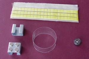 Four pill-size neodymium-iron-boron (NIB, or NdFeB) magnets, from an
electronics shop. They come in a bent strip of iron called a "keeper"
(two are shown here). Also, a plastic ring cut from a small soft-drink
bottle, and some of that sticky stuff normally used for mounting posters
on walls.
Four pill-size neodymium-iron-boron (NIB, or NdFeB) magnets, from an
electronics shop. They come in a bent strip of iron called a "keeper"
(two are shown here). Also, a plastic ring cut from a small soft-drink
bottle, and some of that sticky stuff normally used for mounting posters
on walls.
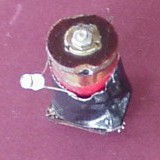
 The coil was wound onto an empty solder spool (remember - I don't throw
things away!), 5cm in diameter and 4.5 cm long, with a central hole 2cm in
diameter.
The coil was wound onto an empty solder spool (remember - I don't throw
things away!), 5cm in diameter and 4.5 cm long, with a central hole 2cm in
diameter.
 ) So I'm
hoping that what I bought is close enough to what's required (they may each
be one gauge too thick).
) So I'm
hoping that what I bought is close enough to what's required (they may each
be one gauge too thick).
 ) so that I could have one hand free to
carefully feed the two strands of wire onto the spool in the required
manner. (I found that surprisingly easy to do, actually!)
) so that I could have one hand free to
carefully feed the two strands of wire onto the spool in the required
manner. (I found that surprisingly easy to do, actually!)
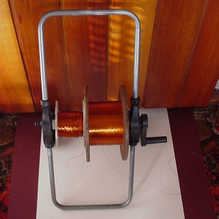 Here you see the two big spools of winding wire mounted on an old hose-reel
frame, in readiness for producing the bifilar coil. Having them organized
this way made the work of winding the coil, using the jig you see above,
quite straightforward. It's well worth taking the trouble to do simple
things like this, to avoid tangles or other disasters.
Here you see the two big spools of winding wire mounted on an old hose-reel
frame, in readiness for producing the bifilar coil. Having them organized
this way made the work of winding the coil, using the jig you see above,
quite straightforward. It's well worth taking the trouble to do simple
things like this, to avoid tangles or other disasters.
 )
)
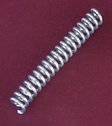 Next: the core. At left you see the gate-closing iron spring mentioned
earlier. I cut it in half and spray-painted it with silver paint to act as
insulation. The two halves screwed together quite easily to make a kind of
tube, 7cm long.
Next: the core. At left you see the gate-closing iron spring mentioned
earlier. I cut it in half and spray-painted it with silver paint to act as
insulation. The two halves screwed together quite easily to make a kind of
tube, 7cm long.
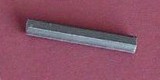 The ferrite rod, slightly longer than 7cm, was wrapped in a piece cut from
a pale blue plastic bag and pushed into the tube.
The ferrite rod, slightly longer than 7cm, was wrapped in a piece cut from
a pale blue plastic bag and pushed into the tube.
 I pushed the cap from an old glue-stick over the "untidy" end, and put a
rubber band around that, to stop it slipping right through the coil. (Later,
I wrapped the core in gaffer tape to make it a tight fit inside the coil,
and eventually dispensed with the cap and rubber band altogether.)
I pushed the cap from an old glue-stick over the "untidy" end, and put a
rubber band around that, to stop it slipping right through the coil. (Later,
I wrapped the core in gaffer tape to make it a tight fit inside the coil,
and eventually dispensed with the cap and rubber band altogether.)
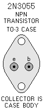 At the heart of the circuit is an NPN power transistor. JB specifies either
an MPS8099 or a 2N3055. I'm familiar with the latter, having used it in
several other projects; so I've used it again here.
At the heart of the circuit is an NPN power transistor. JB specifies either
an MPS8099 or a 2N3055. I'm familiar with the latter, having used it in
several other projects; so I've used it again here.
 (All those poles in
my machine attract the "N" pole of the compass; so see what you make of
that.) Either way, if you do it right, you'll wind up with a "monopole
motor", which is all that really matters in the final analysis!
(All those poles in
my machine attract the "N" pole of the compass; so see what you make of
that.) Either way, if you do it right, you'll wind up with a "monopole
motor", which is all that really matters in the final analysis!

With the core (wrapped in gaffer tape) out of the coil, and placed in
front. (Later, I actually removed some of the gaffer tape from near the
"tidy" end of the coil, because it was simply too tight to push in easily.)
A shot from behind, showing the transistor, battery, coil and core quite
clearly.
The coil was placed on a folded piece cut from one of those rubber
"grip-mats",
to help hold the coil immobilized, before tightening the pipe clamp over
it.
A view of the left-hand end. You can see the potentiometer, switch and
wheel.
(Later I changed to a different switch.) To take this picture, I stood the
motor
on end, using a gel battery to prop it up - that's the large black object at
left.
A close-up from behind, showing some detail of the terminal block.
You can see
the reddish-brown diode with its black band near the potentiometer's
knob, and
close by, the 10-ohm resistor, both connected into the terminal block's
front side.
) Also, I
tried running it from 12-volt lead-acid gel batteries.
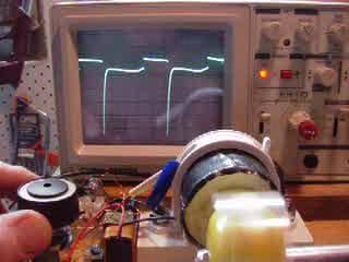 The first movie shows the motor running on an old 9V battery. At left is
the final frame. Each time a magnet interacts with the coil, a
characteristic voltage-pattern - including a sharp transient (which shows
as a "spike") - occurs. Two such transients are visible here.
The first movie shows the motor running on an old 9V battery. At left is
the final frame. Each time a magnet interacts with the coil, a
characteristic voltage-pattern - including a sharp transient (which shows
as a "spike") - occurs. Two such transients are visible here.
)
You can see here how the blue plastic tape which marks one end
of the coil windings eventually came unstuck. I later replaced it
with a paper sticker, coloured blue (visible in later photographs).
). Also, just behind, there's a three-connector
terminal block to accommodate various new connections.
 As soon as I switch on, for the fraction of a second before I set the
wheel spinning you can hear an oscillation whose waveform is clearly
visible on the 'scope; also, the electromagnet's LED glows.
As soon as I switch on, for the fraction of a second before I set the
wheel spinning you can hear an oscillation whose waveform is clearly
visible on the 'scope; also, the electromagnet's LED glows.
 Return to my ZPE researches menu page