
This page added on Friday, 10th July 2009
+
+
+
+
+
As mentioned in the page about my first attempt to build a motor of this
type (see the link above), the word "monopole" as used in this context
does not mean that I believe in the existence of particles which
have the character of either a north pole or a south pole. (I suspect that
such things don't exist; however, I'm not dogmatic about it. See my
second page on
electromagnetism,
about four-fifths of the way down, to read some of my earlier comments on
the subject). The term "monopole" in this context has to do with the fact
that these motors rely heavily on repulsion between either two "north
poles" or two "south poles" of "ordinary" magnets - one, an
electromagnet; and the other, a permanent magnet.
The photograph you see above has already appeared before in this website
in my oddly-named
2
The strange-looking gizmo it depicts is my second attempt to make a motor
of the type described by John Bedini (JB), a US electronics engineer who
claims to have been building such things since 1984.
CAUTION:
There is some risk associated with motors of this type. As JB mentions in
his own writings, it may be possible to receive an electric shock from
them; however, perhaps more significantly, there is a danger of physical
disintegration! These motors can spin very fast, and if they're not
well-built, it's possible that one or more of the magnets attached to the
rotor may go flying off in unpredictable directions. [This hasn't happened
with my first monopole motor (see the first link above), but it did
happen with my second one, which is the subject of this page - and I
consider myself very lucky that my eyes (especially my one "good" eye)
weren't in the "firing line" at the time (more details shortly.)] Or, of
course, the whole rotor may become detached and go spinning out of control
if the motor itself is not sufficiently sturdily built. So, if you build a
motor of this type, be careful; having drawn attention to the possible
dangers, I cannot and will not accept any responsibility if something goes
wrong.
If you don't yet know anything at all about these monopole motors (or
"Bedini motors", as they are also called, after their inventor), may I
recommend that you do, in fact, visit my page (whose link appears above)
about my first motor of this type. That page also contains links to other
websites which provide a good background to the topic.
This second motor is a work in progress. I still have in mind to modify it
in order to improve its performance, even (perhaps!) to the point where it
may actually display the phenomenon known as "over-unity", meaning that
it's tapping into more energy from the zero-point field than it's using
from its battery or other "normal" power-source. I'm not there yet; but I
haven't given up on the idea, either.
Originally, the motor didn't look much like the photo at the top of this
page at all! It's undergone a number of transformations. The following
four photos, of its original incarnation, were taken on 11th November 2008
(you can click on them to see 640×480 versions):
As you can see, it featured another skateboard wheel with four small
NdFeB magnets attached around its rim in the same way as for my first
monopole motor. (This time, just a single wheel was used, attached to a
little wooden pillar I made up specially for the purpose.) Also, the
circuit - built into a five-connector terminal block - was identical with
the one in my first monopole motor, with a 1K linear potentiometer, a
10-ohm resistor, a 1N4148 diode, and a 2N3055 transistor, all mounted in
exactly the same way, with the terminal block mounted on a little wooden
plinth screwed to the base. (There was also an on-board 9V battery,
initially, although this was later removed.) Recall these two diagrams
from my first monopole motor's page; they apply here also:
You may have noticed, in the above photographs, a two-connector terminal
block in front and to the right of the main circuit terminal block; that's
just there to connect the two soldered wires from the switch to the rest
of the circuit. (Experience has taught me to keep soldering to a minimum,
as I'm not really very good at it! Hence the extensive use of terminal
blocks in my projects.) That's a minor difference from my first monopole
motor.
But what is substantially different about this second motor is the
coil.
In my page about the first of these motors, I mentioned that, when I came
to build the second motor's coil, things went rather badly wrong. The time
has now come to tell the story...
The main reason for wanting to build a second monopole motor at all was to
see if I could in fact successfully create one which would charge a
battery - even, perhaps, well enough to qualify as an "over-unity" device.
Having had a bit of a look around the web to see what I could find out
about these Bedini motors, I'd noticed a couple of things:
1.
The coils were often wound onto rather small-diameter formers, with room
for only thin cores - in contrast to my first motor's coil, which was
wound onto an old solder spool with quite a large central hole (about 2cm
in diameter) which thus required a fairly large-diameter core (as detailed
in my page about that motor's construction);
2.
At least one possible scheme for charging a battery with a
motor of this type involved a third winding on the coil, in
addition to its drive (or power) winding and its
trigger winding. This third winding, apparently, would act somewhat
as a secondary winding (as in a transformer) which would experience a
voltage across it as a result of the drive coil's action. The output from
such a winding (with some rectifying circuitry) could, in principle, be
used to charge a battery. If the motor was running from one battery, and
if this third coil could somehow be persuaded to charge a second battery
faster than the first battery ran down, you'd have an over-unity device!
(Click
here
to visit a web-page which presents a circuit for such a "Two Battery
System", near the bottom of the page. The third winding, labelled "Sec
Feedback Coil" - the green one - is what we're talking about here.)
So I decided to build a coil - just a bifilar two-winding coil initially,
as in my first monopole motor - onto a former with a small-diameter
central hole and enough room to add a third winding later, if and when it
became appropriate to do so.
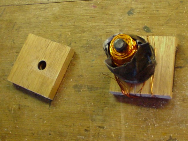
I used an old plastic crayon-barrel as the central tube, and cut two small
square pieces of timber to act as the end-pieces. I drilled central holes
in these two wooden pieces, just big enough to take the crayon-barrel as a
tight fit. I wound some gaffer tape around the tube, and set the whole
thing up in my winding jig as you see here:
Then I started winding the two wires on together, just as I had earlier
for the first motor.
At first everything seemed to be going well. But at some point I noticed
that the left-hand end-piece was moving. Clearly, it wasn't as tight a fit
on the tube as I'd thought! The wire was pushing it outwards.
I kept winding cautiously, but eventually I realized that I had a serious
problem as the situation became worse. I was faced with the choice of
trying to unwind the wire already wound, then reinforcing the former and
starting again - or taking it off the jig as it was, holding it carefully
in one hand and continuing to wind manually with the other.
The first wasn't really an option. It seemed clear that any attempt to
unwind the wire and install the two strands back onto their respective
feeder spools - or even onto a single spool, probably - would almost
certainly result in an unholy tangle in very short order. So I embarked on
the unpleasant task of winding by hand, as quickly but as cautiously as
possible!
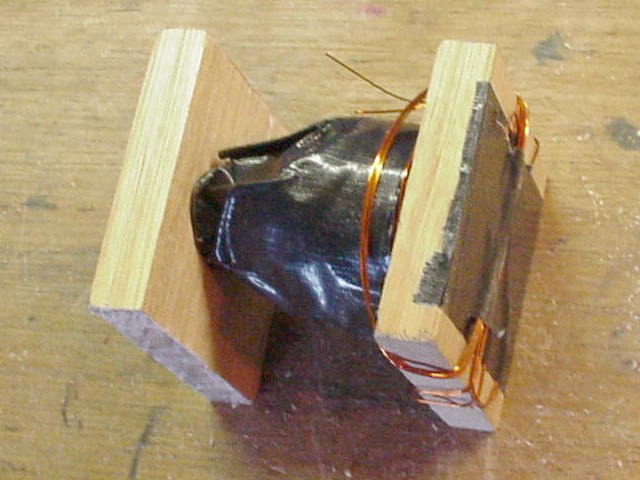
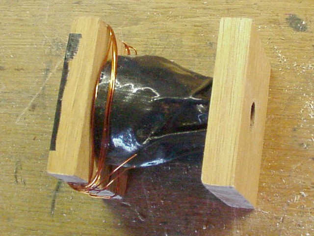
I eventually wound a total of about 600 turns on, trying as hard as I
could to keep most of the wire toward the "good" end of the former. The
result was an ugly conical coil. Almost as soon as I'd finished, I wrapped
it up in gaffer tape to try to prevent it from basically falling apart.
Here are some photographs of the resulting monster (you can click on them
to see 640×480 versions). Don't laugh!
One thing that was very clear was that this was far from being a
high-quality bifilar coil. The early part of the winding was probably
quite good; but when I had to finish it in an angst-ridden state by hand,
I can tell you that the individual strands went all over the place, hardly
staying side-by-side at all. Oh dear!
To be honest, I thought that the coil might end up as a complete waste -
but, as you'll soon see, I was able to get some good use out of it after
all. (No way, however, was I going to try to get a third winding
onto it!
However, I learned one valuable lesson from this: if you are going to wind
a coil onto a former you've made yourself, make absolutely sure
that you've made it well enough to withstand the process. (In my case, I
did have a large bolt through the centre, but neglected to set things up
so that I could screw a corresponding nut tightly against the opposite end
of the former to hold it firmly in place, relying instead on friction. If
I'd taken the extra trouble, I probably would have obtained quite a
respectable result. Next time...)
To stabilize the coil, I cut three pieces of perspex sheet to hold it all
together: a piece to be attached to the top by a brass screw at each
corner, and two smaller pieces to be attached to the sides, near the
bottom, by brass screws at each end. I made these two side pieces wide
enough to fit over the edges of the base-board, and cut slots in them so
that they could slide along screws in the sides of the base-board,
secured on the near side by a wing nut.
I cut a piece of cardboard tube from an old pepper-shaker, just long
enough to fit over the coil, covered it with gaffer tape, and slipped it
over the coil before fixing the whole unit together - partly to make it
look rather good, and partly (if I'm honest) to conceal the evidence!
You can see the finished coil unit in those four earlier photographs of
the motor, above. (Note from those photos that I did indeed use a large
bolt and nut for the core.) So: with the motor completed, I switched on, gave the
wheel a spin...
...And it didn't work!!!
It nearly worked. The wheel spun half-heartedly through a few
revolutions, looking as though it was "trying" to pick up speed - but,
ultimately, it slowed down and stopped. It just "conked out".
I tried several times, to no avail. I assume it was because of the
disastrous coil. I even tried using a piece of ferrite rod - just like the
one I've used for my first monopole motor - for the core, still without
success.
So - what was I to do?
Well, I did what any good inventor does, when faced with a setback. I used
my initiative.
I had some larger NdFeB magnets "lying around". (I'd bought them some
years previously, when I had an inkling that I was going to be getting
into projects that would need them. They're the same type as those used in
modern Faraday torches - click
here
to see my page about such things.)
I also had some empty CD boxes, having bought them from
my favourite Launceston junk shop
a few years back, suspecting that they'd come in useful some day.
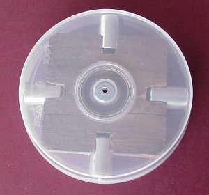
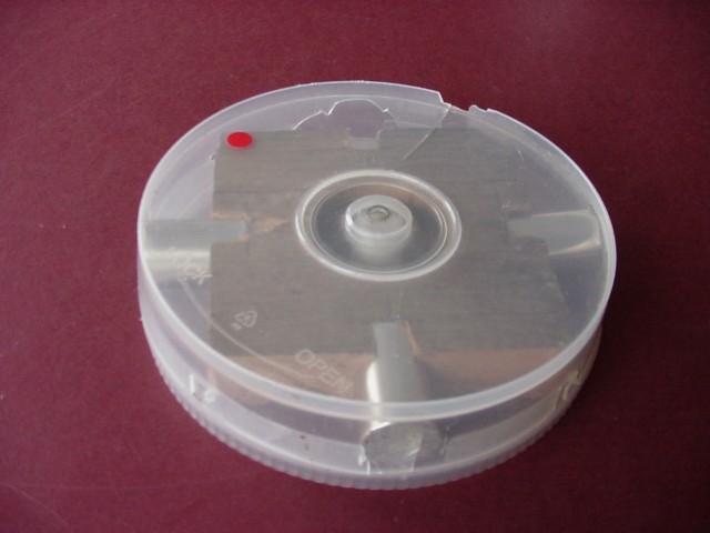
The idea was to fix the magnets in place inside the CD box, equally spaced
around the rim, and all with the same pole facing outwards. (As it turned
out, they were placed so that they attracted the "N" pole of my little
compass, so that this became a "south pole motor" - just the same as my
first monopole motor.) To hold them immobilized inside the box, I used a
piece of old timber which was somewhat the worse for wear (having been
outside in my back garden for ages) but which was pretty much ideal in
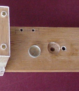
terms of size. I cut a square piece off the end and drilled some suitable
holes: a large central hole (using a hole saw), as there was a flange
inside the box which had to be avoided; and four smaller holes to
accommodate the magnets in the wooden block's edges (I used a spade drill
for this).
(Actually, the piece of wood was so grotty that it fell to pieces while I
was working on it, and had to be glued back together! But I persevered
with it, because in so many ways it was ideal, notwithstanding its age and
condition - and my decision was vindicated by the eventual success of the
rotor. Not pretty, but functional.)
It was quite a difficult job to get them to stay in position. Putting the
last one in was a real battle - one momentary loss of concentration, and
the others would be jumping out all over the place, with a risk of
considerable damage if they should clang together violently. Somehow, I
got them in.
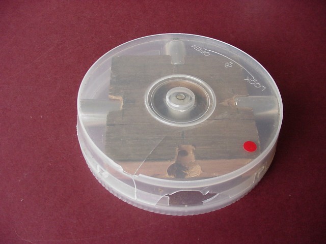
Notice in this picture, and the one above, that there's a small hole
drilled in the centre. This is to accommodate a 75mm-long, 3/16"-diameter
bolt which would form the wheel's axle. I used a short piece of very tough
plastic tubing (the inside end-piece taken from an old crayon) similarly
drilled and pushed into the box's central spindle from below, to act as
the lower grip for the axle.
Note from the first of those two photos that there are four small gaps in
the box's rim (the corners of the wooden block are lined up with them in
that picture). In fact, with the lid partially on, I rotated the block so
that the magnets lined up with those gaps instead, on the principle that
they would stay located that way and thus the block/magnets combination
would not be free to rotate within the box. Hence the magnets were then
actually pressing on the inside of the lid, rather than the
box. (The reason for taking the trouble to point this out will
become clear shortly.)
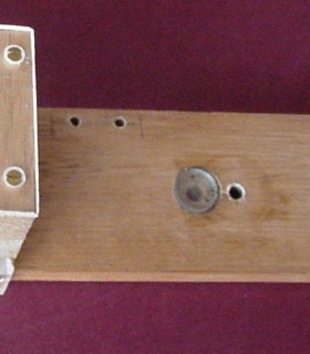
I drilled a hole in the lower limb to take a 25mm-long, 1/4"-diameter
brass bolt, to secure the bracket to the base via a 1/4" brass nut.
As mentioned, the rotor's axle was to be a 3/16" bolt, 75mm long. To act
as bearings, I used four short pieces cut from an old telescopic TV
antenna: two just wide enough to slide easily over the bolt, and two
slightly wider to fit over the first two. These wider pieces were to be a
snug fit in the wooden bracket's top and bottom holes respectively.
I very carefully drilled the lower part of the bottom hole just
wide enough to accommodate a 3/16" dome nut, to be screwed onto the end of
the axle. (The hole's diameter was very slightly larger than that of the
dome nut, so that there would be no contact.) When everything was set up
properly, the round tip of the dome nut would protrude just a millimetre
or so beyond the bottom of the bracket; and also the dome nut could be
pushed up inside so that its tip was a millimetre or so above bracket's
bottom surface. Thus, with the completed bracket/rotor assembly screwed to
the base, the dome nut's tip would be level with the base's top surface
and the rotor would be free to rotate unimpeded.
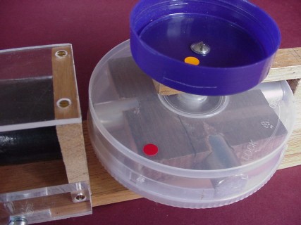
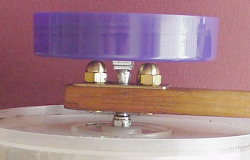
The bluish-violet object, lock-nutted firmly to the top of the axle, is
the lid from a jar of hair-gel, as once used by a junior member of my
family. I drilled a central hole and installed it upside-down, not really
being quite sure why at the time (basically it just looked "cool"!). In
fact, it turned out to be a good idea, as you'll soon see.
The rotor iself was initially mounted onto the axle by lock-nutting pairs
of nuts both above and below, along with some washers. This was a
trial-and-error procedure; several modifications were made over time to
find the best way to achieve this. (There wasn't much room to play with,
to tighten up those nuts. Fine-nosed pliers played a major part in what
was quite a tricky process!)
Eventually, however, I found what seems to be the perfect soloution. We
now live in the era of the
"nyloc nut"
- a nut which incorporates a small ring of nylon. When screwed tightly up
against something, these grip the bolt very firmly, so that one of them
does the same job as two lock-nutted ordinary nuts. Just one on top of the
rotor and one under it are all that is necessary to hold it firmly to the
bolt. This makes the assembly process a great deal easier. (Apparently,
it's recommended to use washers with these nuts; but I haven't done so,
and there doesn't seem to be a problem.)
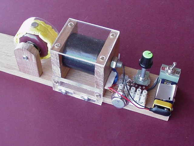
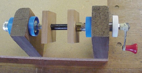
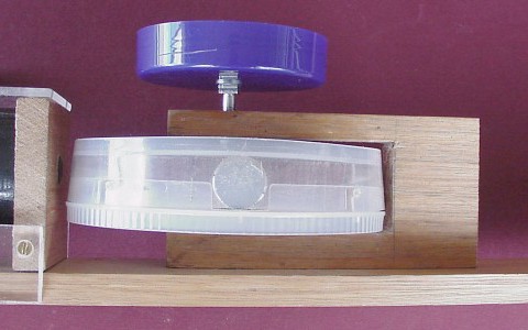
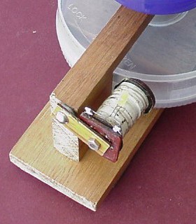
Here's a side view of the entire bracket/rotor assembly:
Next - some details of how it was fixed to the base.
As mentioned, a 25mm, 1/4" brass bolt (with matching nut) was involved. (I
used brass, rather than steel, because it was fairly close to the rotor's
magnets, and I didn't want it to have any effect on the motor's
operation.) In addition, a brass wood-screw was used to hold the body of
the bracket firmly to the base; this was screwed up from underneath.
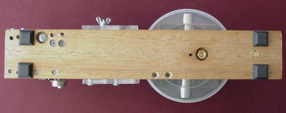
Here's a photo of the underside of the base:
The head of the wood-screw can be seen between the square black feet at
the right-hand end. Note that the brass nut which is screwed onto the 1/4"
brass bolt is set into a small recess, made with the aid of a spade drill.
Also note a small hole just to the left of the nut; this was made as part
of the process of drilling a similar recess in the top of the board, to be
explained next.
(Finally, note two countersunk holes near the lower edge in the photo.
These were the holes for the two screws by which the small pillar which
held the skateboard wheel was originally attached to the base.)
The recess in the upper side of the board was made to take a small glass
disc. If you've visited my first
synchronous wheel
page, you'll have read how some years ago I came into possession of a
number of such discs from a former Launceston glazier. Much as in the case
of that earlier project, I used the disc - with a small amount of grease
on its top surface - to support the rotor's axle:
This formed an excellent bearing for the dome nut on the lower end of the
axle.
So now I had something to try out. By now, the coil's core was a piece of
ferrite rod, just as in the case of my first monopole motor. At some
stage, I also placed a small orange circular sticker into the hair-gel
lid, to serve much the same purpose as the small white sticker on my
synchronous wheel: to give some indication of the motor's speed, when
viewed under a fluorescent light. (I also placed a similar red sticker
onto the rotor itself.)
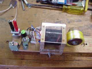
My first experiments with the new motor were conducted on Saturday, 15th
November 2008, using my small 12V gel battery connected to the 9V battery
clip via one of my crocodile-clip leads. I also replaced the trigger
circuit's 100-ohm series resistor with a large old-fashioned resistor from
among my Dad's old things. (That's the red cylindrical object in the
photograph below. I measured its resistance at 315 ohms.) Initially, I
hadn't yet placed the red and orange stickers.
With the motor at maximum speed, I switched off and filmed the early part of
the slowdown - click
here.
(Again, if you've seen the movies toward the end of my second
synchronous wheel
page, you'll probably recognize the style!
By Thursday 20th, I'd dispensed with the idea of using an on-board 9V
battery. (From the first of the two photos above, you can see its clip -
made from the sliding metal cover of a defunct 3.5" floppy disc - at the
left-hand end of the base; this was now removed.) I installed a pair of
banana sockets (red and black) in order to run the motor from an external
power source - either a gel battery, or my
old black power supply
and bridge rectifier.
Also, by now I'd decided to make a series resistance greater than 100 ohms
a permanent feature in the trigger coil circuit, eventually settling on a
normal-sized modern 330-ohm resistor. Again, if I remember rightly, at
some point I managed to burn out the potentiometer (which is probably what
really decided me to use that larger-value series resistor). It didn't cause
a problem, because the motor's "sweet spot" was well within the new range.
(Note that the potentiometer in the following photo is a different one
from that in the earlier pictures.)
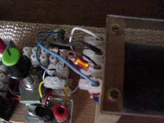
Furthermore, by this time I'd installed a four-connector terminal block
onto the left-hand side of the coil to tidy up its wires, using blue and
white tape to aid in identifying the particular ends of the windings -
just as I later did in my first monopole motor.
Just one other thing - note the small neon light connected into the coil's
terminal block; more about this later.
+
+
+
+
+
By now, I was running the machine from my old black power supply and
bridge rectifier on a regular basis, with the power supply's voltage set
to 14V AC (thus providing nearly 20V DC from the bridge rectifier). I
found it interesting to lower my head to bench level and observe the edge
of the rotor at close quarters. From oscilloscope traces (about which more
later), I'd figured out that the rotor was regularly spinning at well over
4,000 rpm - and I was trying various tricks to get it to spin even faster.
At some point while the motor was running, I squirted some silicone spray
lubricant into the bearings. I was alarmed to hear the speed increase very
rapidly, and reached over to my left to switch the motor off - too late!!!
There was a cracking sound, and one of the magnets shot out of the
rotor, hit me in the tummy, bounced off and promptly disappeared - while
the motor ground to a very shaky halt over a few seconds.
Fortunately, my tummy is pretty well padded, and I wasn't hurt. However,
it's a sobering thought that not long before, I'd had my eyes level with
the spinning rotor...
I think someone was looking after me that day!
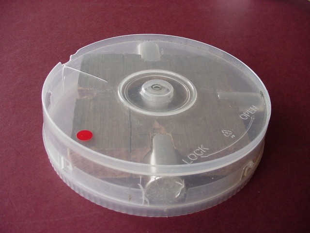
After I'd recovered my wits, I looked carefully at what was left of the
rotor and noticed that the centrifugal effect of all three of the
other magnets had been causing damage to the box (to its lid, mainly, as
that was what the magnets were pressing against). Any one of them
may have been just about "ready to go".
Here are photographs of the rotor taken from the perspective of each
magnet position in turn, for comparison. (Click on them to see 640×480
versions.)
That still left the problem of: where did the missing magnet go?
It could have shot across my garage/workshop and broken the window; or it
could have hit the concrete wall; or it could have headed for and damaged
my car - any number of things. There was the distinct possibility that, if
it had hit something hard, it could have disintegrated into lots of sharp,
dangerous, strong little magnets, scattered all over the (rather untidy)
area.
But luckily, it didn't. It hit my ample midriff, probably thereby losing
quite a bit of its kinetic energy, and then went - where???
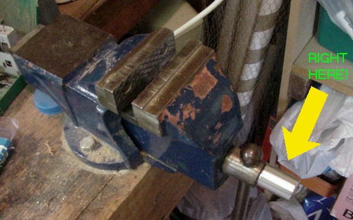
I eventually found it. It had stuck itself onto my bench vice, completely
intact, remarkably without either causing or experiencing any damage at
all!
As I've said - I think someone was definitely looking out for me
that day.
At the risk of being tedious, again may I urge you to be very
careful if you are intending to build your own Bedini motors - or,
indeed, if you intend to undertake any form of potentially
dangerous experimentation. The health and safety of yourself and those
around you must come first. Think before you act; and never
take silly risks - it's just not worth it!
So - I was faced with the prospect of building a new rotor.
Fortunately, I had what I needed. I'd bought three CD boxes of that size
and shape, so I still had two left. This time, however, I was going to
make sure the rotor was reinforced, to (hopefully) prevent any further
accidents!
Among the many bits'n'pieces I'd found among my Dad's old things were some
rolls of strip metal. Most of these were attracted to magnets, and were
thus almost certainly iron; whatever they were, they weren't suitable for
this purpose because I needed something non-ferromagnetic. However, there
was one roll of strip metal which appeared to fit the bill perfectly.
I weighed the strip metal and obtained an estimate of its volume by water
displacement, and was thus able to get a good estimate of its density. I
did a Google search on metal densities and found that magnesium has a
density of 1.74g/cc. My density estimate was very close (just a little
lower).
I concluded that it was almost certainly magnesium, as there is no other
common metal with such a low density that also has good structural
strength. (I resisted the temptation to follow the example of Archimedes
and go running down the street in my birthday suit yelling
"Eureka!"
when I'd figured this out.)
The strip's width was ideal - it would just fit into the CD box. I cut a
piece long enough to go around inside the box twice, put it in, and then
placed the wooden block with its four magnets inside that. It was a
perfect fit.
I cut four small rectangles from a clear plastic fruit-juice bottle and
slipped them between the ends of the magnets and the magnesium strip, to
eliminate any possible corrosion which might occur over time as a result
of the difference in electrochemical potential of the two metals
(magnesium, and the nickel casing of the magnets).
I then put the lid on (which was quite a struggle, as things were now a
bit tight). With the axle-holes drilled and the tough plastic tube from
the original spindle installed underneath, I had a new rotor ready for
action - and, so far, it has stood up to the challenge very well!
(I didn't bother to put a red sticker onto the new rotor, as the original
one hadn't really been visible when the motor was running, being too close
to the edge and thus moving too fast to see.)
Initially, it appeared that the wheel might pick up speed - but it slowed
over about 20 seconds and then stopped, just as before. Maybe one day,
with a decent coil, it'll work...
So I just went ahead and installed the new rotor. I also added an extra
feature.
If you've visited my page about my first monopole motor, you'll have read
about how I arranged for it to interact with an electromagnet with a
light-emitting diode (LED) soldered to its coil's ends. That electromagnet
was one of two that had once served as chokes in a battery eliminator for
my first transistor radio, nearly four decades earlier; the other one was
now called upon to perform a similar function in this project.
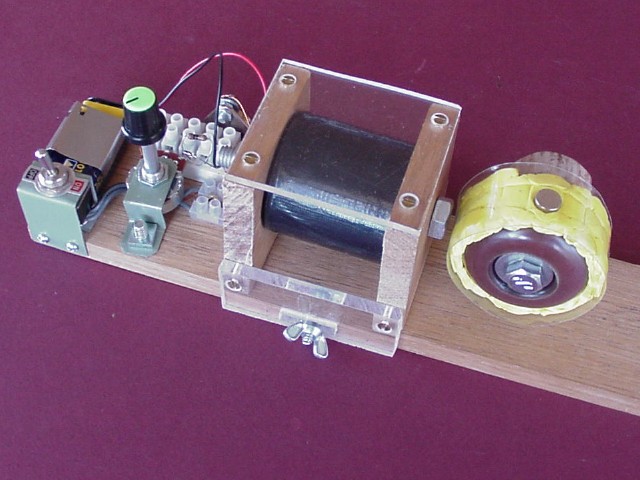
It's attached to the top of the rotor's bracket via a small piece of
laminated plastic and a couple of screws. (You can just see the yellow LED
against the white tape in which the electromagnet is wrapped.)
The electromagnet can swivel up (on top of the bracket) or down (behind
the bracket). When it's up, it has little or no interaction with the
rotor's magnets; when it's down, the magnets induce a voltage sufficient
to light the LED. (There is then a considerable braking effect on the
rotor.)
Over time, I noticed that the rotor's bearings were becoming more noisy,
presumably due to wear. The top one, at least, was reasonably accessible,
and I made an improvement by drilling the hole a bit larger and bolting a
piece cut from the end of an old brass mortise lock's face-plate onto the
top of the bracket, so that its original screw-hole was centred over the
hole in the bracket. A slightly longer piece cut from the larger of the
two tubes from the TV antenna was a snug fit in the screw-hole, and
replaced the original piece. I used 3/16" brass bolts and dome nuts to
secure the plate.
I'm still not sure how, if at all, I can do anything to improve matters at
the lower bearing. If I could find some way to secure the outer metal tube
firmly inside the bracket's hole, it would probably help. The way it is,
sometimes it remains stationary inside the hole; but sometimes it spins
within the hole - outside the smaller tube - creating a vibration or
"buzz" which represents wasted energy. (It's more of a nuisance than
anything else - it can stay in the too-hard basket for now.)
Both types have 3/16" thread; but the axle's nut (left) was physically
slightly smaller, also brass but (apparently) chrome-plated.
Having overcome various setbacks and actually produced quite a reasonable
little project, even with its substandard coil, I began to wonder
if there was any chance that it may actually be possible to persuade it to
charge a run-down battery, at least to some extent.
As mentioned, I'd already discounted the feasibility of adding a third
winding to the coil. However, while hunting for information about monopole
motors on the web, I'd run across at least one other way to extract an
electrical output without the necessity for any further windings;
click
here
or
here
to see a circuit diagram for such a device.
So I decided to modify my second motor's circuit to make it somewhat
similar to the one shown in those web-pages.
Until then, the circuit for my second motor was almost exactly the same as
the one for my first motor. The "hardware" aspects - the coil, the rotor,
and the overall layout - were obviously quite different; but from a purely
electronic point of view, they were very similar. The main points of
difference were that the 10-ohm series resistor had been replaced by a
330-ohm resistor, and there was no longer an on-board battery, with two
banana sockets provided instead to allow external connection to a battery
or other DC power source.
Also, as mentioned earlier, I'd added a small neon light bulb, connected
between the transistor's collector and emitter. I'd read somewhere (I
can't remember where) that it's a good idea to do this, as it provides a
"sink" to discharge excess energy in the form of high voltages which can
otherwise damage components, the transistor in particular. (I'd already
"fried" one transistor!) The neon light is connected into the coil's
terminal block across the "blue tape" ends of the two windings.
The circuit diagram for the project thus far is as follows:
So now I added a 1N4007 diode and another pair of banana sockets into
which a battery may be plugged for charging. The following circuit diagram
shows these two new components:
There are three differences between this circuit and the one shown in the
above links: that circuit has a 100-ohm resistor (where I'd originally had
a 10-ohm resistor, later replaced with a 330-ohm resistor); I haven't
added an incandescent light bulb into the trigger circuit, as has been
done in the other circuit (apparently this is not considered essential);
and I've kept the original 1N4148 diode (the other circuit has a 1N4001).
I decided not to change these on the principle that one should add as few
new variables as possible when setting up a new experiment.
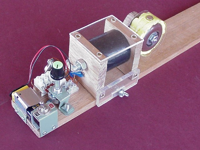
I located the new banana terminals at the front edge of the base-board. In
order to accommodate the new diode in a tidy way, I introduced another
two-connector terminal block which I mounted above the one which connects
to the switch.
I also added a four-connector block into the small amount of remaining
available space between the power terminals and the switch, at the
left-hand end of the base, and made connections to the points shown as A,
B, C, and D in the circuit diagram. I made four small wire loops and
connected them into the left-hand side of the terminal block. The purpose
of this is to make it easier to connect an oscilloscope probe or
multimeter etc. to various points of interest in the circuit while
testing.
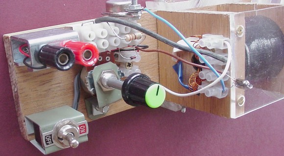
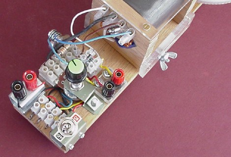
You can see all these new features in the following photograph:
The question that arises is: how, if at all, can such a circuit charge a
second battery?
It's a very reasonable question. On the face of it, that's a very odd
circuit indeed. Note from the circuit diagram that, when the motor is
running, the negative terminal of the charging battery is connected to the
positive terminal of the power battery (or whatever other DC power source
is being used). Presumably, then, the circuit is somehow generating a
larger DC voltage across the charging battery than the applied
voltage at the power terminals. What's going on?
Note that it takes about 70 volts to "strike" a neon light. (Click
here
to see the 1.3Mb, 15-second movie.)
So it's clear that there is a voltage of at least 70V at the
collector/drive coil junction (B, on the circuit diagram) relative to the
power supply negative (D) - enough to make the neon light glow, quite
brightly. (In fact, that neon light, initially a clear little glass bulb,
quite quickly became clouded to a dull grey soon after I installed it, as
a result of metal vaporization and deposition on the inside of the glass.
The fact that its glow is still bright enough to be seen very clearly
through the darkened glass speaks volumes.)
Just by the way - I have managed to give myself a shock from the circuit
once. Sometimes, I've placed a finger on the body of the transistor (i.e.
its collector) to see if it's getting warm. On one such occasion, I got
quite a strong jolt from it! Why it happened then, but not at other times,
I don't know. (I've had a similar experience before from one of my other
little motors; visit
this page,
down toward the bottom, to read the details.) Luckily, no harm done, on
either occasion! Maybe this time I'll learn from the experience...
So that quite high voltage - rectified by a diode - is fed directly to the
charging battery. Does it work?
On Monday, 24th November 2008, I decided to give it a try.
It was down to less than half a volt. I tried to charge it using my
ordinary battery charger, to no avail. Apparently, I'd bought a real dud.
In his writings, JB claims to have resurrected sick batteries using
monopole motors. I decided it was worth a try.
At that stage, the neon light was in place, but I hadn't yet permanently
connected the second diode. I took my old power supply and bridge
rectifier out to the back garden, along with the motor, my multimeter, the
afore-mentioned second diode, the useless battery, and several crocodile
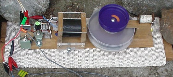
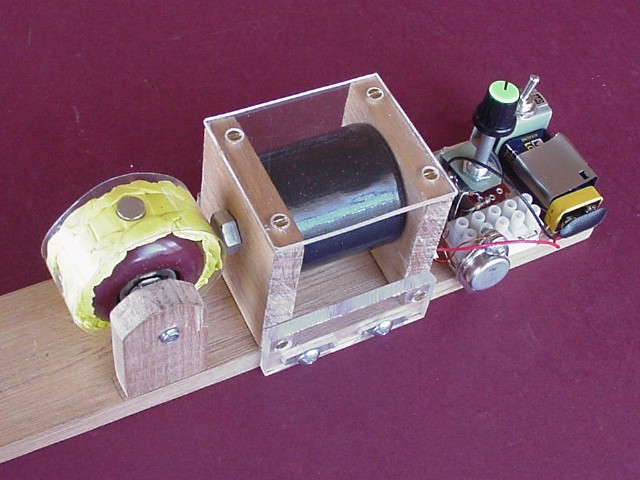
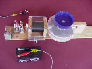
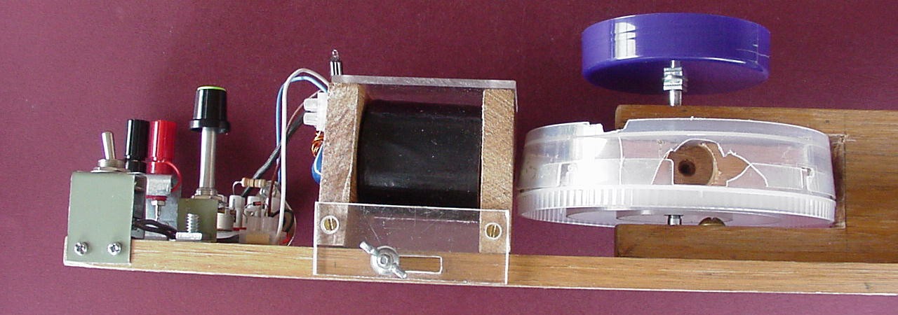
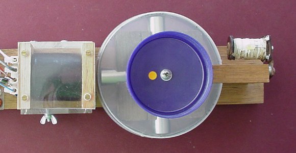
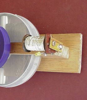
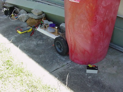
clip leads, and set everything up. The photo at the top of this page shows
some of the resulting arrangement; the following one shows the whole
set-up:
For the same reason, I placed the battery behind the tough wheelie-bin, just to
protect all the other bits and pieces from being blown to smithereens
should the worst happen.
I needn't have worried. I had it running out there for over three hours,
checking the battery's voltage every now and then with the multimeter.
Here are my notes:
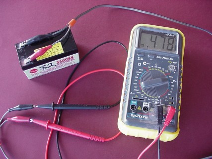
Charging of sick 12V battery, 24-11-2008, using MPM2
Started at approx. 11:30 a.m. - battery initially at 0.478V. Charge voltage
showing at 32.6V.
At approx. 12:35 p.m., disconnected battery from MPM2 and measured 4.4V
(6.0V initially, dropping down over about a minute to a steady 4.4V)
Reconnected battery to MPM2 at approx. 12:40 p.m. Charge voltage at 27V.
At approx. 1:50 p.m., repeated above procedure and measured 4.4V; charging
voltage was 23.8V.
At approx. 2:50 p.m., voltages were 4.9V and 24.6V. Shortly after
switch-off, battery voltage had dropped to 3.2V. Later dropped to 2V.
Earlier I presented an mpeg movie which shows this motor running from
another small 12V gel battery. This one started life as quite a
gutsy little energy-source; but I think I damaged it by using it too much
and then neglecting to charge it (using my ordinary battery charger) soon
enough thereafter. The result is that its voltage went down to less than
10V, and it wouldn't charge back up to 12V (the charger's LED blinked,
indicating that it "thought" the battery was fully charged, when it quite
clearly wasn't).
On Saturday, 28th March 2009, I set everything up again outside (can't be
too careful) and put the motor to work trying to rejuvenate that small gel
battery (as before, parked behind the ubiquitous wheelie-bin, just in
case). I ran it for over two and a half hours, and the battery's voltage
went up from about 9.8V to about 10.3V - in increase of about half a volt.
Again, nothing spectacular; and it still won't respond to my
ordinary charger after the event - but it did manage to hang onto that
extra half a volt when I checked it two days later.
It's interesting to note that the charging voltage - as shown on the
multimeter - was about 12.7V (as compared to over 30V, on the earlier
occasion when I tried to charge the really sick battery), and that
the neon light didn't glow this time (which it had done with the other
battery).
From the notes above, it's quite clear that the charging voltage - as
measured on my multimeter - drops significantly as the battery begins to
charge up, seeming to indicate a definite resistance to being further
charged. I've no idea how to explain the actual figures in any detail -
how much of it is due to high-voltage spikes (i.e. high voltage) from the
motor, and how much is due to any low-voltage content (perhaps at a higher
current). Neither can I account for the fact that the neon light doesn't
glow when the charging battery is close to its nominal voltage.
Quite clearly, these are complex issues, and I can't draw any definite
conclusions. (Perhaps when I build a better coil I'll get better results.)
But it is interesting and fun to be engaged in my own modest
scientific research project!
Obviously, there's lots of room for serious research here - and I'm
probably not really equipped to do this properly. It is my fervent hope
that "mainstream science" will begin to take these and related phenomena
seriously very soon, hopefully in time to see a well-organized zero-point
energy industry adopted world-wide before it really is too late, and
damage from global warming due to the burning of fossil fuels becomes
permanent.
This is turning into another of my l-o-n-g pages, isn't it? However,
please bear with me - there's not too far to go. I'm deliberately going
into considerable detail, in the hope that you - and anyone else you tell
about it - will get involved and build your own monopole motor and then
find some way to go public about it, as I am doing right here, in the hope
that enough such activity will finally get the world's "movers and
shakers" to wake up and get behind ZPE research As Soon As
Possible.
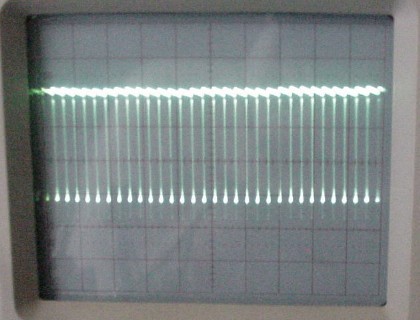
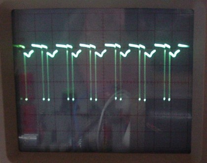
A few details about what actually happens when this motor is operated:
(Click on the photo to zoom up on the oscilloscope screen.)
The oscilloscope's time-base is set to 2 milliseconds (2ms) per division.
Since there are 10 divisions (square-widths) across the screen, this means
that the beam makes one complete left-to-right sweep in 20ms. If you look
at the right-hand half of the screen, you can count 16 "spikes" occurring
over 10ms, or one-hundredth of a second. So the frequency of oscillation
is 1,600 Hz (cycles per second).
Since "concert pitch" ("A440", or A above middle C) is 440Hz, we can
calculate the approximate note produced by the motor as follows:
2n/12 = 1600/440 = 3.636363...
- or about 22 semitones above A440. This is a high G, nearly two octaves
above A440. (An octave is 12 semitones.)
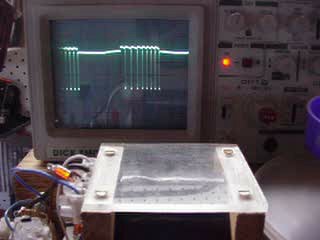
As it speeds up, the trace begins to take on the character of a standard
monopole motor waveform (see photos on my
first monopole motor
page for comparison).
The oscillations stop as a magnet moves away from the core, and recommence
as the next magnet approaches.
(Click on the photo to see a close-up of the 'scope screen.)
The speed of rotation can be estimated from the trace. The time taken from
a particular magnet's interaction with the coil to its next
interaction (count the "double-spikes" as 1, 2, 3, 4, 1) is about six
divisions, or 12 milliseconds. This corresponds to a rotational speed of
1000/12 = 83.333... revolutions per second, or 60×83.333... = 5,000 revs
per minute (rpm). (It's actually slightly faster, because the time per
revolution is slightly less than six divisions.)
Click
here
to see a 1.3Mb, 15 sec. mpeg movie showing the motor running at top
speed. A few seconds into the movie, I switch the motor off, and it begins
to slow down. Then I switch on again, and it speeds up again. What's
interesting is that the trace shows some electrical activity even when the
motor is off but still spinning. (In fact, the neon light even glows very
slightly during that time, but it's too faint to be seen in the movie.)
Note that, in all photos and movies so far in this page showing the motor
running from my old black power supply, I have it set to a nominal voltage
of 14 volts AC, which gives a DC measurement of 16 volts - as shown on my
multimeter - across the power terminals with the motor running. With a
5-amp DC ammeter in the circuit, I obtain a DC current reading of 0.3 amp.
So the motor is drawing about 4.8 watts - just 8%, or about one-twelfth,
of the power used by a 60-watt light bulb.
I've done a similar measurement with the power supply turned up to its
maximum voltage setting (20 volts AC). In this case, with the motor
running, I get a reading of 24 volts DC at the power terminals and a
current of 0.4 amp; thus the motor is drawing 9.6 watts from the power
supply (just twice as much as for the above scenario). With this set-up,
the motor runs at one revolution in 10 milliseconds, i.e. at 6,000 rpm (as
opposed to 5,000) - and that's pretty scary, sounding rather like some
kind of power-tool. (Click
here
to see an mpeg movie.) I don't leave it running at that speed for any
length of time, just in case. (In fact, on occasion I've been able to get
it to spin with the wheel completing a revolution in 9 milliseconds,
corresponding to a speed of 6,666 rpm - and that is really freaky!)
Here are some links to other web-pages which are well worth a visit.
Initially, just look them over to get the gist of what they're about, then
perhaps read parts of them in more detail to get ideas for your own
researches. (But don't get too bogged down in them, because they're
basically discussion pages, and they tend to be a bit "rambling" by their
very nature.)
http://www.energeticforum.com/renewable-energy/364-bedini-sg.html
http://www.energeticforum.com/renewable-energy/366-bedini-solid-state-oscillators-2.html
http://radiant.100free.com/zpe_bedini_solid.html
http://www.energeticforum.com/renewable-energy/366-bedini-solid-state-oscillators.html#post4023
http://72.52.145.132/renewable-energy/2003-free-energy-last-step-step-must-see-15.html
http://www.overunity.com/index.php?topic=6688.msg159178
Now, some links to YouTube videos.
First, an interview with John Bedini:
http://www.youtube.com/watch?v=0PBHePZ_6U8&NR=1
Second, an animation which explains the operation of a motor which is
charging a battery:
http://www.youtube.com/watch?v=yi7cmUpMdX8&NR=1
Third, a "slide show" of several circuit diagrams for variants of the
basic monopole motor circuit:
http://www.youtube.com/watch?v=Ee9uYqFb-OI&NR=1
Fourth - I'm not sure what's going on here, but about halfway
through the video things get pretty spectacular!
http://www.youtube.com/watch?v=grQVV6hvvgo&NR=1
Fifth - this is a funny one. The guy has put something together that looks
anything but neat and tidy, but claims that he's charging a battery very
nicely. Well worth a look, and you'll get a chuckle out of it.
http://www.youtube.com/watch?v=qMB-MIiCzio
Sixth - this looks very impressive. As the video points out, nobody can
prove to anybody else that these things really work as claimed - you have
to do that for yourself. I get the distinct impression that he's made his
point very well.
http://www.youtube.com/watch?v=Zv1npBgWEbk&NR=1
Seventh - this one gives a big raspberry to the "Mythbusters" TV program
which claims to have "busted" the Bedini motor. This fellow has a sense of
humour, a bit of attitude, and a working machine: "You didn't build it
right..."; "It's not perpetual motion, it's not free energy, but it
charges batteries..." (One of the best of these videos, in my opinion.)
http://www.youtube.com/watch?v=QHfftseq908&feature=related
It's worth reading the bulletin board comments on that page. There's no
shortage of people who are delighted to pour scorn on the video and its
makers, but who (a) have never actually built a model to prove or disprove
the claims, and/or (b) are missing the point that no-one is
claiming to be creating energy - merely channeling it from one
place to another.
On the seventh page of those comments is one which appears to be from the
video's authors which I think sums the matter up very well:
All I can say is that the "secret" lies in the magnets, I guess. A small amount of energy pulls them,
but as they pass, a larger amount is discharged somehow...
Some of the video's critics decried the fact that they were using their
car battery to power the motor, and only charging small batteries,
suggesting that they could probably have achieved the same result by using
the car battery directly, without the need for the motor. A second video
addresses that criticism by having both the drive battery and the charging
battery of the same type - both small gel batteries. It's well worth a
look:
http://www.youtube.com/watch?v=xRavED3KVKc&NR=1
- and, interestingly, most of the cynics seem to have faded away!
One more from these characters - they've added a second coil with its own
circuit (as each coil needs its own), and their bicycle wheel spins
quite a lot faster as a result:
http://www.youtube.com/watch?v=kx1BOd_mnJk&NR=1
That's enough video links to be going on with - there are plenty more
which you can find within those YouTube pages, and of course you can use a
search engine to dig out even more for yourself.
Finally, a link to a web-page which discusses the "bust" mentioned above,
among other disturbing matters. Perhaps the most important of these links;
PLEASE READ:
http://www.panacea-bocaf.org/johnbedini.htm
Also, follow the links within that page - especially the one about the
Mythbusters.
SUMMARY AND CONCLUSION
In this page, and the page about my
first monopole motor,
I have simply given an account of my own first attempts to follow in the
footsteps of others who claim to have found a way to tap into zero-point
energy. I'm not making any claim to have produced an "over-unity" model of
my own. I may eventually succeed in doing so; or I may not. [Bear in mind
that John Bedini (JB), the monopole motor's inventor, has been engaged in
this research since 1984 - a quarter of a century ago.]
The important thing is that the existence of ZPE is accepted,
albeit somewhat uneasily, by the mainstream scientific community; and that
serious, sincere interest has been expressed over time by respected
scientists in the notion that it may well be possible to put ZPE to work
as a clean, safe, sustainable source of practical energy for our everyday
needs. (The names Werner Heisenberg, Arthur C. Clarke, Hal Puthoff, and of
course Nikola Tesla - among others - come to mind in this regard.)
It is time for mainstream science to embrace these ideas. It is also time
for our political and business leaders to get involved to make it happen.
With our world facing environmental disaster - as is now becoming
increasingly clear, as day follows day - we can't afford to sit on our
hands any longer.
By drawing attention to one possible means of accessing ZPE - the monopole
motor - I'm simply trying to help spark a movement of concerned citizens
to force our leaders to take the matter seriously. It's not particularly
difficult or expensive to make a model which at least illustrates the
basic principle. If enough people around the world get involved with this,
and make a point of going public about it - as I am doing via this website
- just maybe we can get the attention of those with the real power
to bring it about, sooner rather than later. The need is urgent and the
time is short.
That's my challenge. Please - get involved. Build a model yourself - or
encourage technically-minded people you know to do so, if you don't feel
up to it yourself - and spread the word. If you do succeed in
making a viable machine which taps into ZPE well enough to be
"self-sustaining", yell about it! Show it off in public; get the press,
radio, or television involved; exhibit it in a science museum if you can;
put it on your own website - anything, to help get the message out.
With a global community of people doing what they can to draw attention to
the need for properly-funded, globally-coordinated ZPE research, the
"movers and shakers" won't be able to push the matter aside for much
longer. The time to act is now.
My home page
Preliminaries (Copyright, Safety)
 Mad Teddy's researches
into zero-point energy
My second "monopole motor"
>>>
Nikola Tesla's 153rd birthday
<<<
To begin - a few preliminaries. The first few paragraphs in this
page are very similar to the corresponding paragraphs in my
My first monopole motor
page, because - as in that page - there are some important things that
need to be said to avoid misunderstandings, and in the interests of
safety. So, apologies for being a bore and pretty much repeating myself; I
wouldn't do so if I didn't think it was essential.
 ×251 + 1 = 7
 ×41
page, posted in January 2009 to welcome in the new year. Now, the time
has come to post a web-page addressing its subject matter in some detail.
×41
page, posted in January 2009 to welcome in the new year. Now, the time
has come to post a web-page addressing its subject matter in some detail.


 )
)
 I figured that with one of these, and four of
those powerful magnets, I could put together a rotor which might work
even with that crummy coil.
I figured that with one of these, and four of
those powerful magnets, I could put together a rotor which might work
even with that crummy coil.
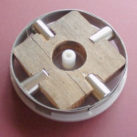
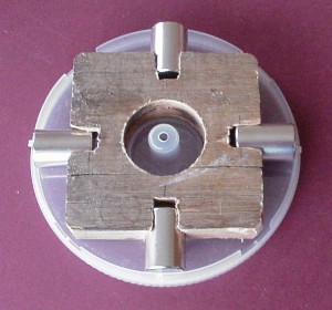 Here you can see the box with the square piece of old wood, drilled as
described above, with its four powerful magnets - which were repelling
each other furiously!
Here you can see the box with the square piece of old wood, drilled as
described above, with its four powerful magnets - which were repelling
each other furiously!
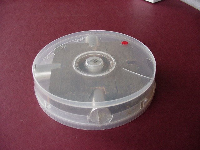
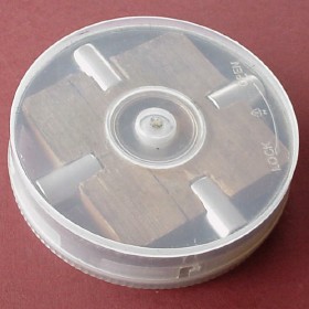
 Here's the box with the lid safely in place. (That was quite a relief!)
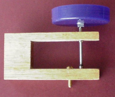 To mount the rotor, I cut a piece of 19mm timber and carefully drilled a
hole through its entire width, only then cutting out a piece to
accommodate the rotor. This was to make absolutely sure that the top and
bottom holes would line up accurately.
To mount the rotor, I cut a piece of 19mm timber and carefully drilled a
hole through its entire width, only then cutting out a piece to
accommodate the rotor. This was to make absolutely sure that the top and
bottom holes would line up accurately.
Showing the disc next to the recess...
...and in situ
 There was an audible oscillation (as there had been when running my
first monopole motor from a gel battery). I gave the rotor a spin.
To my huge delight, it kept spinning - and speeded up quite dramatically!
Click
here
to see a 15-second, 1.3Mb mpeg movie.
There was an audible oscillation (as there had been when running my
first monopole motor from a gel battery). I gave the rotor a spin.
To my huge delight, it kept spinning - and speeded up quite dramatically!
Click
here
to see a 15-second, 1.3Mb mpeg movie.
 At some stage during the day's proceedings, I put the red and orange
stickers onto the rotor, and took more movies showing the rotor both
speeding up and slowing down. Click
here
and
here
to see them.
At some stage during the day's proceedings, I put the red and orange
stickers onto the rotor, and took more movies showing the rotor both
speeding up and slowing down. Click
here
and
here
to see them.
 )
)
Click on the picture to see the original full-size photograph
(Reconstruction - another magnet placed there later and photographed)
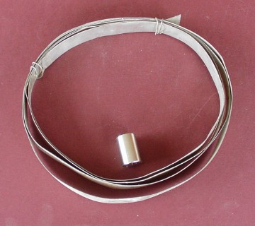 As you can see, that strip metal and an NdFeB magnet are blithely ignoring
each other.
As you can see, that strip metal and an NdFeB magnet are blithely ignoring
each other.
 It was now Friday, 21st November 2008. I decided that, before installing
the new rotor, it would be interesting to have one last try with the
skateboard wheel. Click
here
to see the result (1.3Mb, 15 sec).
It was now Friday, 21st November 2008. I decided that, before installing
the new rotor, it would be interesting to have one last try with the
skateboard wheel. Click
here
to see the result (1.3Mb, 15 sec).
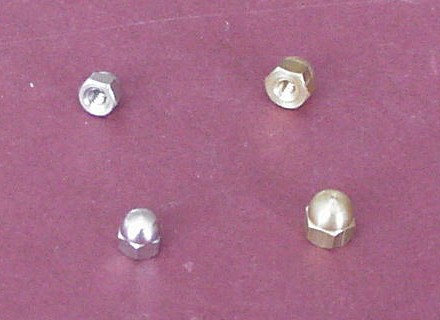 It's perhaps worth mentioning that those dome nuts (right) are not the
same as the one used for the lower end of the axle.
It's perhaps worth mentioning that those dome nuts (right) are not the
same as the one used for the lower end of the axle.
 This photo is one frame from an mpeg movie showing the motor being
switched on and then started spinning by hand. The neon light can be seen
glowing with neon's characteristic orange glow, flickering slowly at first
and then faster as the motor speeds up.
This photo is one frame from an mpeg movie showing the motor being
switched on and then started spinning by hand. The neon light can be seen
glowing with neon's characteristic orange glow, flickering slowly at first
and then faster as the motor speeds up.
The muffled music at the start is coming from my son's
computer in the room above - he was "YouTube-ing".

 Some time before, I'd done a very silly thing and purchased a second-hand
12V gel battery from "you-know-where" and found, to my very unreasonable
annoyance, that it was as flat as the proverbial pancake. (Granted, it
only cost me two lousy bucks - but it was the principle of the
thing that galled me.)
Some time before, I'd done a very silly thing and purchased a second-hand
12V gel battery from "you-know-where" and found, to my very unreasonable
annoyance, that it was as flat as the proverbial pancake. (Granted, it
only cost me two lousy bucks - but it was the principle of the
thing that galled me.)
 I made a point of doing the experiment outside, just in case it was
too successful - with the battery perhaps exploding.
I made a point of doing the experiment outside, just in case it was
too successful - with the battery perhaps exploding.
(BTW - that wheelie-bin is the subject of one of my poems; click
here
to read it.)


Nothing to get too excited about, really! I suspect that the battery was
simply too far gone to be rescued. (Since then, it's dropped back down to
about 0.43 volts.)
 As already mentioned, the motor oscillates, or "sings", when it's first
switched on. I hooked up an oscilloscope probe across the drive coil and
took some pictures of the waveform; this is the best one I could get.
As already mentioned, the motor oscillates, or "sings", when it's first
switched on. I hooked up an oscilloscope probe across the drive coil and
took some pictures of the waveform; this is the best one I could get.
=> n/12 = ln3.636363.../ln2 = 1.3625 (approx)
=> n = 22.35
 Click
here
to see an mpeg movie (1.3Mb, 15 sec.) of the waveform generated by giving
the rotor an initial spin from an initial "high-G" standing start. (The photo at left is one
frame from that movie.)
Click
here
to see an mpeg movie (1.3Mb, 15 sec.) of the waveform generated by giving
the rotor an initial spin from an initial "high-G" standing start. (The photo at left is one
frame from that movie.)
 With the rotor at maximum speed, there's only time for two "spikes" per
quarter-revolution. You can see how the waveform has assumed the familiar
shape - other than the fact that there's not just one spike, but two, each
time.
With the rotor at maximum speed, there's only time for two "spikes" per
quarter-revolution. You can see how the waveform has assumed the familiar
shape - other than the fact that there's not just one spike, but two, each
time.
As I've mentioned elsewhere, many claimed ZPE devices combine the dual
attributes of permanent magnets and high-voltage transients. This is
definitely the case with Bedini monopole motors. So it's my strong sense
that the author of that comment has absolutely hit the nail on the head
there. (Again, may I remind you of Heisenberg's assertion that we could
utilize magnets as an energy source.)
 MAD TEDDY
Celebrating life
on the spectrum
and trying to help save the world -
with
junk
 Return to my ZPE researches menu page