
If you came here by way of my
Electrical stuff
menu, you will have seen a
photograph of the front cover of "Model Making For Young Physicists" by
A.D.Bulman (John Murray, 1963). That front cover featured a drawing of the
project about to be described here.
It's a very simple project, but it needs to be well-made if it is to perform
satisfactorily, because it generates very little power - and every milliwatt
is precious.
(Now, why do those last four words remind me of Monty Python??)
If it's made without attention to detail, it probably won't work at all.
On the other hand, if it is made carefully, it can be a source of
great fascination. Simple it may be; but it's possible to do quite a lot of
very interesting physics with it. (I'd like to think that science teachers
may find it a source of inspiration.)
My own model started out pretty much as Bulman described it, and worked
reasonably well for a while. Over time, however, the second law of
thermodynamics took its toll: parts wore out or went rusty. Eventually the
electromagnet was removed and used for something else, with the remaining
bits tied together with a piece of wire, stored away and forgotten about.
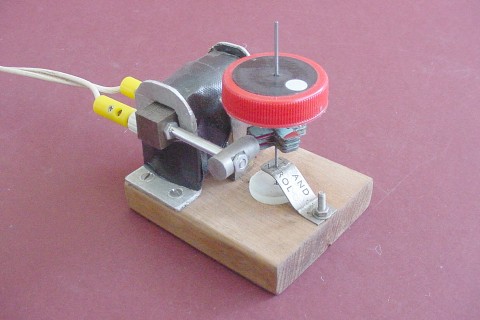
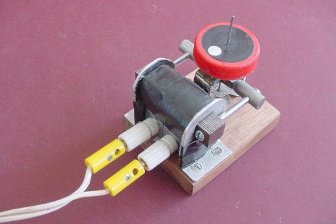
In 2002, I found it and decided that it would be fun to get it going again.
After a few hours of re-building, fiddling and adjusting, I came up with a
pretty neat little gadget. Here it is:
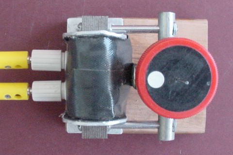
The spindle consists of a large sewing needle with the eye cut off. Onto
this is fixed a cross made from twelve small plates cut from thin sheet
iron, each 25mm x 6mm (1" x 0.25"). Each of these plates has a small central
hole, just big enough for the needle to pass through. The plates are stacked
up as laminations so that they run alternately "north-south" and
"east-west".
The iron sheet we (my Dad and I) used for the laminations was taken from a
spool which at some stage had probably held a length of wire. The outside of
this spool was painted pale blue with red markings (as can be seen from the
picture above). This layer of paint probably helps (if only slightly) the
performance of the model, as it provides a layer of insulation between the
plates and thus helps to minimize eddy currents which could have a dampening
effect.
I'm not quite sure how my Dad fixed the cross to the needle. He probably
followed Bulman's instructions fairly closely, the cross being wired in
place while being soldered, in the hope that enough solder would hold the
strips in place on the needle. Or perhaps he just glued it together with
epoxy glue - I'm not sure. Whatever he did, it was a neat and effective job;
and the whole assembly has stood the test of time extremely well!
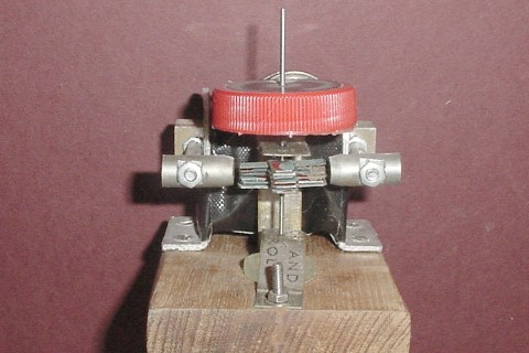
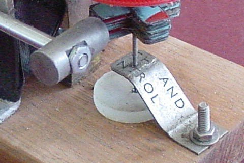
In this next photograph, you can see the construction of the cross quite
clearly.
You can also see the upper support, which is attached to the base under the
electromagnet by a couple of nuts, bolts and washers. This is bent up at
right-angles to rise between the rotor and the electromagnet; finally,
another right-angle bend completes the zigzag, and the rotor is supported by
a hole drilled in the top horizontal section.
Actually, when I revamped the model, I reinforced this upper support by
attaching another short piece of brass strip as a strut to produce a
triangle, as shown here:
This adds considerably to the overall robustness of the model.
You can also see a smaller brass strip, bent into a serpentine curve with a
small hole drilled at one end to lend support to the lower end of the rotor.
The strip is attached to the base by a single bolt through a larger hole at
its other end (more about this shortly).
In Bulman's original model, there was no lower support strip. His model
relied on the upper support and a strip of brass with a small indentation to
support the needle at its point.
(Also, his upper support was attached near the edge of the base, where our
lower support was attached).
The original flywheel was made from a disc of hardboard 0.6cm (0.25") thick
and 3.2cm (1.25") in diameter. The needle was passed through a small central
hole, and the disc glued in place. Like the cross, this has lasted well
also.
The flywheel was painted white, with a red circular dot painted near the
edge above one of the cross-arms. (The reason for this will be explained
shortly.) When I revamped the model in 2002, I added a 4cm diameter red
plastic bottle cap with a central hole, which fits quite snugly over the
hardboard disc, and placed on it a 3.2cm white circular sticker which I had
coloured black with a marker pen. I then placed a smaller (8mm diameter)
white circular sticker on the black one, near to the edge, and again above
one of the cross-arms. Part of the reason for doing all this was that the
old flywheel was a bit tatty, and I decided that the whole thing could do
with a face-lift. It turns out that the extra mass also provides a stronger
flywheel effect (i.e. more angular momentum), which I think is probably a
good thing.
In the original model, made following Bulman's instructions fairly closely,
the point of the needle rested on a strip of brass of the same type as the
supports, attached to the base by a couple of small screws. A small
indentation was made in this brass strip for the needle point to rest in.
The problem with this was that, over time, the spinning needle drilled
itself deeper into the soft brass strip until it actually became a rather
tight fit, completely defeating the strip's purpose. One could always replace
it; but it occurred to me that it was possible to do a lot better.
There used to be a glazier's shop in my home city; sadly, this became just
another victim of economic rationalism and globalization a few years ago.
On occasion, I'd buy various little things from them for various projects.
One such project (I won't go into detail) required small glass discs. It
turned out that, from time to time, the glazier found it necessary to bore
holes in sheets of glass to meet some customer's special needs. They put
the resulting discs aside and eventually threw them out.
Ever on the lookout for useful bits and pieces, I asked if I could have some
of these little discs. Sure enough, they gave me quite a lot!
One of these discs found its way into this project. Using a glass drill, I
made a small conical depression in one side. I placed a circular sticker on
the other side, and glued it to the base with ordinary wood/paper glue so
that, with the needle vertical, its point would rest in the depression.
I mentioned earlier that I'd have something more to say about the lower
support for the rotor.
Theoretically, the lower support is not necessary. (This was obviously
Bulman's point of view, too.) If the needle point is sitting in the conical
depression in the glass disc, and the rotor is supported above the cross,
why would it need any other support?
The reason is that the rotor is started spinning by a quick twist with thumb
and forefinger
("Here comes the twister"
Once the rotor is spinning, however, the lower support becomes redundant.
Therefore, it's highly desirable that the needle should not touch the sides
of the hole once it is released, so as to reduce overall frictional losses.
By attaching the lower support to the base firmly, but at a single point,
it's quite easy to adjust things so that this requirement is met.
Now: to the electromagnet.
An old soldering iron I'd had since the early 1970's eventually wore out to
the point where it was no longer a going concern. At some stage in the early
1990's, I pensioned it off and bought a modern temperature-controlled
Dick Smith solder station.
I don't throw old things out. (My wife calls me a "hoarder".) So I still had
the beat-up old soldering iron lying around in 2002, when I decided to
rescue the synchronous wheel.
The soldering iron had its own transformer, which I dismantled as carefully
as possible. A hacksaw was needed to cut through the laminations - a
somewhat hair-raising job, if one is to avoid damaging the windings. This
successfully accomplished, I unwound the wire. I used half of the primary
winding to make the electromagnet for this project, and eventually used the
other half for the next project described in this website (the
single-solenoid electric engine
). The thick, short secondary I put aside. (It may see service as the
primary of a Tesla coil at some later stage.)
I don't know exactly how many turns there are on my electromagnet. Bulman
suggests winding on from 300 to 600 turns.
I used a section of the laminated core of the now defunct tranformer as the
core for my new eletromagnet. I prepared two ends from a piece of aluminium
sheet, and placed them on the laminations. I covered that part of the
laminations between the ends, and the insides of the aluminium ends
themselves, with gaffer tape, and wound the wire on, finishing the work with
a covering of more gaffer tape over the windings.
The piece of transformer core I used already had holes drilled in its ends;
bolts had passed through these in the original transformer, to hold it
together. I passed long steel bolts through these holes, added a nut to each
to anchor the bolts firmly to the core, and then placed pieces of
chrome-plated brass tubing liberated from an old telescopic TV antenna over
the bolts for most of their length.
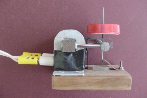
I had a couple of large-diameter bolts left over from an earlier project.
The first couple of centimetres of these bolts, next to the heads, was
unthreaded. I cut the heads off, and also cut the threaded sections off,
leaving two short rods each tapered at one end. I used a file to make flat
areas on each of these near the untapered ends, and drilled holes to
accommodate the long bolts. Finally I used nuts to secure these rods onto
the long bolts to give the structure you can see in the photographs.
I used pieces cut from small right-angle shelving brackets bolted to the
aluminium end-pieces as supports for the white banana socket terminals, to
which I then connected the ends of the winding. Finally, I added some more
gaffer tape to give a tidy finish to the lower part of the structure, and
attached the whole thing to the base with four screws, two at each end.
I've gone into considerable detail regarding the constuction of this
project. Why?
Well, basically because I feel that if you only build one of the little
mechanical models described in this website, this one has the most to offer
from a scientific point of view. If you do decide to build your own
synchronous wheel, I'd like to try to ensure (as far as possible) that it
works well, so that you may have as enjoyable and educational an experience
from its use as I've had from mine.
It's necessary to have a source of AC power to operate the synchronous
wheel. Mine runs very nicely from
my old power supply
. Because of the need for AC, the bridge rectifier is not used.
If you have access to an AC power supply, you're in business. If you don't
have one, you can probably obtain a suitable plug-pack with an AC output.
With my power supply set to its 14V output, the model draws about half an
amp (which means that it's then running at about 7 watts).
All set?
So, you switch on, give the rotor a twist, and away it goes! Right?
Not quite. You need to spin it at just the right speed, with very little
room for error. However, if you do, it will indeed keep on spinning!
So what is the right speed?
This has to do with the frequency of the AC supply in your area. In
Australia, where I live, and in some other countries including the UK, the
frequency is 50Hz (i.e. 50 cycles per second). In the US and other
countries, the frequency is 60Hz.
In each cycle (1/50 or 1/60 of a second, depending on where you live),
current flows in the coil first in one direction and then the other, in a
smoothly-varying sinusoidal fashion. As a result, a
sinusoidally-varying magnetic field (denoted by B, and measured in
teslas) is generated between the poles of the elecromagnet, first in
one direction (north-south) and then in the other (south-north).
The critical point here is that a strong magnetic field occurs twice
within each cycle: one-quarter of the way through the cycle, and
three-quarters of the way through it, as indicated in the diagram above. The
fact that the field's direction reverses every time is immaterial for our
purposes; the cross laminations are made up from un-magnetized soft iron,
which will happily line up with a magnetic field oriented in either
direction.
Thus a magnetic field capable of lining up a set of cross laminations in any
one of four rotor orientations, 90 degrees apart, occurs 100 (or 120) times
each second.
Now, the cross has four arms, each of which passes each of the two poles of
the electromagnet on each revolution. If the rotor is spinning so that the
arms of the cross are close to the electromagnet poles each time the field
strength is at a maximum, and are as far away as they can be (i.e. at a
45-degree angle to the direction of the magnetic field) when when the field
strength drops to zero, it must be spinning at one-half of a turn per AC
cycle. This means that it will be spinning at 25 revs/sec (or 30 revs/sec).
Hence, under these conditions, the speed of rotation, in revs/sec, is
exactly half the frequency of the AC supply, in Hz (cycles per second).
Whenever the rotor is spinning, there are forces (friction with the upper
bearing and the glass disc, air resistance) tending to slow it down. If it
is spinning as just described, the repeated pull of the magnet on the cross
laminations as they approach the poles will give the rotor just enough
angular acceleration to overcome these losses, and thus take it safely
through its next quarter-turn. This condition, in which the rotor is always
"playing catch-up" with the AC power supply, produces synchronization and
hence constant-speed rotation.
So: how do you get the rotor spinning at just the right speed, so that it
will "lock in" and continue to spin at that speed? And how will you know
when you've got it right?
Simply spinning it at a somewhat greater speed, and waiting for it to slow
down to the correct speed and settle there, rarely if ever works. It will
just slow down through that particular speed, and ultimately stop -
unless you're very lucky (it's happened for me just twice).
It requires practice and a deft touch to spin it just right. It's not easy
at first, as you are guessing how fast to spin it, trying to acquire the
technique, learning from experience - and you may ask yourself:
"How do I work this?"
Believe me - you will know when you've spun it at just the right speed.
Within a fraction of a second, you will be aware that the little machine is
settling into a rhythm.
You may happen to spin it so close to the required speed that it just sits
there and continues to spin quietly as though it were the most natural thing
in the world. You will experience a deep feeling of inner peace.
If you've spun at it just the merest fraction slower or faster than its
required speed, you will become aware of a soft, slow throbbing sound
("whirr-whirr-whirr") as it alternately spins slightly faster and slightly
slower, gradually - over several seconds - settling down until everything is
in equilibrium. Then all you will hear will be the quiet, jiggly little
noise of the spinning needle as it lightly interacts with its bearings, and
the sound of your own breath as you slowly exhale in a sigh of satisfaction.
Spiritual stuff!
Of course, having done it once, and got the "feel" of how to do it, the
learning curve rapidly becomes easier.
Same as it ever was...
Is there any way to simplify this learning experience? Indeed there is - and
this is where the dot on the flywheel comes into its own.
Assume for the moment that the rotor is already spinning as described above,
at half the AC frequency. Suppose also that ambient light is at a fairly low
level, and that a fluorescent light is used to illuminate the model. What
will you see?
No doubt you are aware that the light from a fluorescent tube is not steady,
but flickers. (It can get quite annoying after a while.) How fast does it
flicker?
A moment's thought will convince you that it flickers at double the mains
frequency - for exactly the same reason that the magnetic field strength of
the synchronous wheel's electromagnet achieves its maximum strength at
double the mains frequency.
Now, since the flywheel makes one complete revolution over two complete AC
cycles, and since the light from the fluorescent tube is at its brightest
four times within those two cycles, it follows that the flywheel is
illuminated brightly four times during those two cycles.
Thus you will see the white dot illuminated brightly four times within one
revolution of the flywheel. This means that you seem to see four whitish
areas, apparently stationary, spaced at 90 degree intervals around the
flywheel.
You won't see four sharply-defined circular white dots, as shown in the
left-hand diagram below; but rather a ring composed of varying shades of
grey, with four quite bright patches and four rather dark patches within it,
somewhat like the diagram at the right.
In fact, even that is not quite correct. You will actually see something
like the right-hand diagram above - but rotated a bit. If the flywheel is
spinning clockwise, it will appear rotated slightly anticlockwise, as in the
left-hand diagram below. Conversely, if it is spinning anticlockwise, it
will appear with a slight clockwise twist, as in the right-hand diagram
below.
Why does this happen? As John Lennon once said, "You might well arsk". We'll
deal with the phenomenon in the next page.
If you've made a synchronous wheel of your own following these notes, and
had a bit of a play with it, you may be interested in further activities
involving it. If so, click on this link:
Mad Teddy's synchronous wheel, page 2
My home page
Preliminaries (Copyright, Safety)
My synchronous wheel (ca. 1967)

Ignore the stack of coins peeping out above the flywheel - they're just
propping the model up, as I had it standing on end while I took the picture!

 ).
No matter how carefully this is done, it is very difficult
to avoid a certain jerkiness in the action, so that the needle point will
quite likely not come to rest in the small depression. (It may even be
damaged during the process, if too much vigour is used.) So the lower
support is invaluable for keeping everything more or less in place during
this operation.
).
No matter how carefully this is done, it is very difficult
to avoid a certain jerkiness in the action, so that the needle point will
quite likely not come to rest in the small depression. (It may even be
damaged during the process, if too much vigour is used.) So the lower
support is invaluable for keeping everything more or less in place during
this operation.


 Return to Electromechanical models sub-menu