
Two of the three books mentioned in the lead-up to this page, "Model Making
for Young Physicists" by A.D.Bulman and "The Boy Electrician" by Alfred P.
Morgan, each presented a model which could be described as a "solenoid
engine". The most obvious difference between them is that one of them
(Bulman's) had only one solenoid, while Morgan's had two. The most obvious
thing that they had in common is that they both relied on moving
contacts.
Having built my
two-pole electric motor
, and thus knowing the hassles moving contacts can cause, I decided in 2002
to build a solenoid engine built on very different principles.
The fact is, my Dad and I did build a single-solenoid engine in the late
1960's, based somewhat along the lines of Bulman's model, using an old
solenoid my Dad had lying around (goodness only knows where he got it from,
or what its original function was!). The model did work, although not very
well; eventually it was dismantled, and some of the parts found other uses.
As you've probably guessed, the moving contacts were the main cause of its
ultimate demise.
Reduced to its bare essentials, a solenoid engine of the moving-contact type
can be represented as in the following diagram:
At the right is the solenoid - a coil of wire wound on a tube of
suitable non-ferrous material with a movable soft-iron core. This is
attached to a crankshaft (at left) which bears a slip-ring and a cam, both
made from some suitable metal (eg. brass) and electrically connected
together.
Here is a view from above:
Two brushes made from some springy metal are attached to the base so that
one is in permanent contact with the slip-ring, and the other is in contact
with the cam for exactly half the time when the engine is in operation. In
the above diagram, the relationship of the cam to the crankshaft is such
that the solenoid will pull only when the crank is above the level of
the bearings. In this configuration, the pull of the solenoid on the
armature - and hence the crank - will cause clockwise rotation of the
crankshaft, together with the slip-ring, cam and flywheel. Once the crank
has been pulled to the right-hand horizontal position, the cam is no longer
in contact with its brush and the solenoid is switched off. The flywheel
causes the crankshaft to continue to rotate (or "free-wheel") clockwise
until the crank is horizontal again, but this time over to the left. While
this is happening, the armature pulls the moving core part-way out of the
coil. Then the cam and brush will again come into contact, switching the
solenoid on so that once again it pulls - and the cycle continues until the
power is switched off.
If the cam were mounted at 180 degrees to the position shown here, the
solenoid would pull only when the crank was below the level of the
bearings, and the rotation would be anticlockwise instead.
The model my Dad and I built was pretty much along the lines of the diagrams
above. There may have been minor differences: the slip-ring and the cam may
have been at interchanged positions on the axle; we may have used a second
slip-ring with a semi-cylindrical piece of metal instead of an actual cam -
small details like that - I really can't remember; but the basic idea was
the same. (We probably tried various modifications at different times in an
attempt to improve the performance of the thing!)
It is possible to build a model which has a different geometry, but
essentially the same basic structure. The model described above looks
rather like an old-fashioned horizontal steam-engine. On the other hand,
another experimenter
(see his own
website
) has built an electric engine model which is more reminiscent of a Texan
oil pump! The movie of this is well worth a look - you can see the action of
the cam very clearly.
(While you're there, check out the movie of his Atkinson engine - nothing to
do with the present topic, but fascinating in its own right. Lots of other
interesting things there too - spend a bit of time having a poke around.)
In 2002, it occurred to me that it should be possible to build a machine of
this basic type without moving contacts, using opto-electronic
components to control the switching. Light-Emitting Diodes (LED's) have been
around for decades; so also have Light-Dependent Resistors (LDR's). Both are
reasonably cheap and can be obtained from electronics shops.
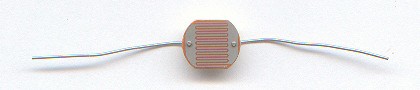
An LDR is a thin slice of cadmium sulphide (CdS), a light-sensitive
substance, mounted on a small piece of insulating material and with two
interleaved metal grids attached to the top surface. When light falls on the
LDR, the resistance between the grids drops dramatically.
This LDR is about 1cm across. In darkness, its resistance is about 45
kilohms (probably more in pitch-dark conditions); with a bright white LED
shining on it at close range, the resistance drops to about 80 ohms.
In the 1960's, when the tremolo effect was popular with electric guitarists
(remember Hank B. Marvin's style in some tunes by the Shadows, or
"Crimson and Clover"
by Tommy James and the Shondells?), technically-minded "musos" who owned
a "basic" guitar amplifier would sometimes add this effect by building an
oscillator circuit capable of flashing a small torch globe (this was
before LED's were common or cheap). The globe would be organized to shine
on an LDR which was wired into the amplifier's gain control, thus
producing the characteristic pulsating effect.
These days, of course, you can buy things like "opto-transistors" which do
essentially the same job as an LDR wired into a gain-control circuit, but
with everything built into a single integrated-circuit package and made from
more recently-developed materials with faster response times.
(By the way: I recently visited a museum which had a display of old-style
pigments used for making paints. Powdered cadmium sulphide is - or was -
used to make bright yellow paint! So I wonder if my use of a yellow LED to
shine on the LDR was an inspired guess - or whether a different
colour would have actually been better? Something to look into at some
stage...)
A circuit including an LDR can be used to control an electric engine. All
that is needed is some method of automatically controlling when a beam of
light from a LED falls on the LDR, connected so as to switch the solenoid on
and off at the appropriate times. What can be used for such a purpose?
From time to time, for other projects (unrelated to those in these pages), I
do a bit of resin casting with clear epoxy-resin. Of course, one always
makes up a bit more than is actually needed, to make sure that there is in
fact enough for the job in hand. Thus there will be a small amount left over
afterwards. Rather than throwing the excess away, I pour it into some small
container - a cap from an old spray-can, for example - and leave it to set,
on the very sound principle that "you never know when it might come in
handy".
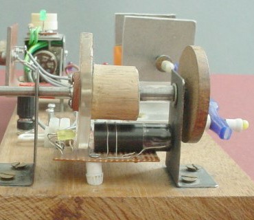
Well, a clear plastic disc made in this way did come in handy - just
the job for the light-shutter in my single-solenoid engine!
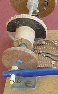
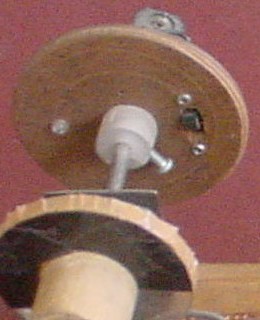
In the left-hand picture above you can see the clear resin disc, with about
half its area covered with black insulating tape. The right-hand picture
shows how a yellow LED is mounted to one side of the disc so that it can
shine into a black tube on the other side, provided the black tape is
not in the way. An LDR, of the same type as that shown above, is mounted
inside the tube, at the far end.
The LED shines all the time while the engine is running. Thus, for about
half the time when the rotor is spinning, the LDR's resistance is high; and
for the rest of the time, its resistance is low.
The resin disc was attached with four screws to a short piece cut from an
old broom-stick. A hole of an appropriate size was drilled through the
centre of the assembly so that it would be a snug push-fit on the metal rod
chosen for the axle. When it turned out not to be quite as tight a fit as
I'd hoped, I included the fibre part of a tap washer in the assembly to
improve matters. (This is just barely visible in the right-hand photograph
above. You can see it better in the final photo in this page.)
Part of the barrel from an old ballpoint pen was used as the distance-piece
between the piece of broom-stick and one of the bearings, as can be seen
quite clearly in these photographs (especially the right-hand one).
In the left-hand photograph above, you can see part of a hardboard disc on
the far end of the axle. This corresponds to the flywheel in the earlier
diagrams. It has its own points of interest; more about it later.
The crankshaft arrangement shown in those earlier diagrams was not used.
Instead, another small hardboard disc with a central hole, and another hole
drilled near the circumference to accommodate a suitable pivot made from a
piece of an old ballpoint pen, was fitted to the near end of the axle as
seen in the left-hand photograph above. (The small blue circle in the centre
of the disc is also a part from a ballpoint pen, included to improve the
disc's grip on the axle.)
The blue object used for the armature is just the handle of an old
toothbrush! I simply cut off and discarded the head, and drilled appropriate
holes in the ends of the handle.
(You've probably noticed some other bits'n'pieces in the top-left quarter
of the right-hand picture above; don't worry about these for the moment -
we'll get back to them soon.)
For the solenoid itself, I used wire which had originally been about half of
the primary winding of an old soldering-iron transformer which I had
dismantled earlier. (Visit my
synchronous wheel
page to see what happened to the other half.)
Originally, I wound the wire onto part of the plastic barrel of an old
ballpoint pen (probably the same one which had provided the distance-piece
mentioned earlier). However, this turned out to be a bad idea. In use, the
solenoid became rather hot, and the plastic tube melted! This led me
to two conclusions: firstly, I was going to need to make the solenoid from
more robust components; and secondly, whatever the solenoid was made from,
it was going to get hot during use, and I would be well advised to install
some sort of automatic switch-off system. (This second point ultimately led
to the use of a thermostat switch - more on this weird saga later!)
Eventually, I used an 8.4cm piece of chrome-plated brass tube which had once
been part of a telescopic antenna on a small B&W television. (Again, check
out my
synchronous wheel
page to see what happened to other lengths cut from this old antenna.)
I had originally used a couple of little wooden blocks to support the
plastic tube, before it melted. Now, I obtained a piece of 1cm-thick
aluminium plate, about 11cm x 5.5cm, and cut it into two approximately
square halves. Having drilled a hole in the centre of each to accommodate an
end of the tube as a snug fit, I assembled the structure and wound the wire
on. I used a couple of pieces cut from "L" cross-section aluminium brace to
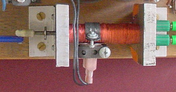
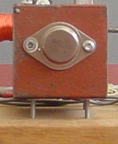
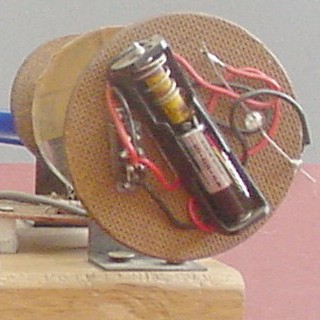
attach the result to the base. Here is a view from above:
The ends of the winding were connected to two green banana sockets attached
to the right-hand support below the coil.
Remember the thermostat I mentioned earlier? Here you see it for the first
time, clamped to the coil. (Just ignore it for the moment, okay?)
Also, here you get your first look at the iron core which moves backwards
and forwards within the solenoid when the engine is running, and which
operates the rotor via the amazing blue toothbrush-handle armature!
The core was made from an odd object I found lying around in my "junk"
collection: a large iron nail with a circular flange a short distance from
the point. I cut the head off and tidied up the cut end with a file. I found
a small piece of plastic shaped like a tube closed at one end (probably yet
another part of an old ballpoint pen!), and found that the point of the nail
fitted tightly in the open end. There was a small hole in the closed end,
just big enough to allow a small bolt to be screwed in, thus tapping its own
thread. The hole in the solenoid end of the toothbrush armature was made
just big enough to allow this bolt to pass through easily.
Now: more detail on how the LED / LDR combination controls the action.
The simplest thing to do would be to put the LDR in series with the
solenoid. It might work; however, the resistance of the LDR is still around
80 ohms when it's illuminated - quite a bit higher than that of the
solenoid's coil. This means that much of the available power will go into
heating the LDR, quite possibly damaging it - and not going to the coil,
where it's wanted. So we'd lose twice.
No: there's a much better way. Instead of using the LDR as a series resistor
for the solenoid, I used a 2N3055 NPN power transistor, employing the LDR -
and a few other components - to control that. As it turns out, this
protects the LDR from high currents, as well as getting plenty of power to
the coil. The 2N3055 is a fairly sturdy device, quite adequate for
controlling the solenoid's power requirements.
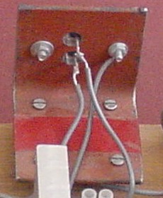
Because the transistor is being called upon to conduct a fairly heavy
current, I've mounted it on an L-shaped bracket cut from the end of a long
heavy iron brace, to act as a heatsink. This is probably overkill; but it's
better to be safe than sorry...
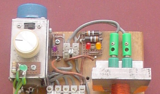
Here is the transistor mounted on its heatsink, both from in front and from
behind:
The base is connected to an old-fashioned 200 ohm resistor (and you know
where I found it, don't you?
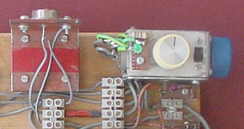
In this picture, taken from above the model, you can see the transistor on
its heatsink; the 200 ohm resistor (red with a black band, connected between
two terminal blocks); and a metal box which contains the 5K potentiometer.
Note: the blue knob at the right controls this 5K "pot", which has a long
shank. The pot itself is mounted in the left-hand end of the box. (The other
knob, on top of the box, controls another potentiometer which will be
discussed shortly.)
At this point, all the essential items required to make the basic engine
have been described. Here, then, is a circuit diagram for the original
version of the project:
(The power switch in the positive rail is on the back of the 5K pot.)
I ran it off my
old black power supply
with my home-built bridge rectifier, set to the maximum voltage (about
27V). It worked reasonably well. As expected, the coil became quite warm,
which ultimately led me to think of a way to include an automatic
temperature control using a thermostat. However, another issue began to play
at the corners of my mind. Although the overall performance was not too bad,
there was room for improvement: the engine seemed to run "a bit rough".
The first thing to do was to build a flywheel. This turned into a little
project in its own right. It started out simply as a circular piece of
hardboard mounted on the far end of the axle, but it acquired a bit more
personality later - more on this shortly.
Even with the flywheel, I felt that it should be possible to make the engine
work more smoothly. I placed more black tape on the transparent disc, so
that light would get through for a bit less than half the time. This
was because the solenoid was obviously staying on for a bit too long, and
preventing the rotor from free-wheeling as well as it should for the second
half of the cycle. This also helped to some extent; but I still believed
that it should be possible to do even better.
I started experimenting with extra resistors between the 5K pot's wiper and
the negative rail. This had a marked effect, and ultimately led to the
inclusion of a 1K linear pot. For different settings of the speed control
(5k pot), this gave a "fine-tune" control. Not a perfect solution - a bit
clumsy - but interesting, and not too difficult to implement.
I built the 1K pot into a small metal box, which now houses both pots and a
small double-pole slider switch. This was included for flexibility: the 1K
pot could thus easily be switched in or out of circuit, as required. I used
the second pole of the switch to run a green LED in series with a 560 ohm
resistor to act as an indicator, showing at a glance when the 1K pot was in
circuit - and also because I just like coloured LED's everywhere!
While on the coloured LED "kick", I included two more LED's - one orange and
one red - each with its own 390 ohm series resistor. The orange one glows
strongly when the transistor is on (and the solenoid is pulling); the red
one glows strongly when it's not. I found that when the fine-tune control
was used to give maximum smoothness, these would flash to approximately
equal brightness, thus giving a good visual indication of correct setting.
I also included one more LED: a white one, coloured purple with a felt pen,
in series with a 680 ohm resistor, to act as a pilot light for the entire
unit.
Here is the circuit diagram for the unit with all these features built in:
Now: as promised, a bit about the flywheel.
Ever the light-show freak, I decided to embed a white LED into the flywheel.
This necessitated an independent power supply to run it. I installed an AA
cell holder on the back of the flywheel, and placed a small 12V battery and
a 560 ohm resistor inside it. A small slider switch was installed. When this
simple circuit is switched on, and the engine set in motion, a ring of white
light appears. (This looks really good in the dark, with all the other LED's
glowing at the same time.)
Here are photographs of the flywheel, from in front and behind:
Because of the weight of the battery, the flywheel is not perfectly
balanced. I've put this fact to good use by arranging that, when the engine
is switched off, it comes to rest with the armature in a good position to
re-start it when power is re-applied. (I've found that the engine runs
better when set up to rotate anticlockwise, as seen from the front.)
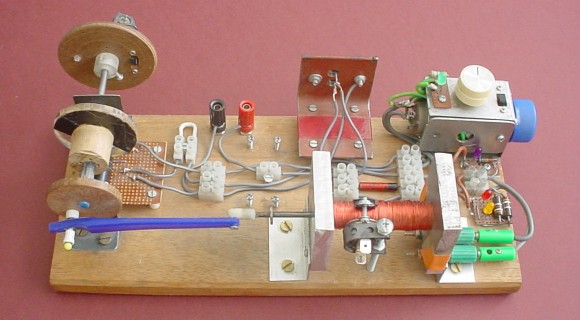
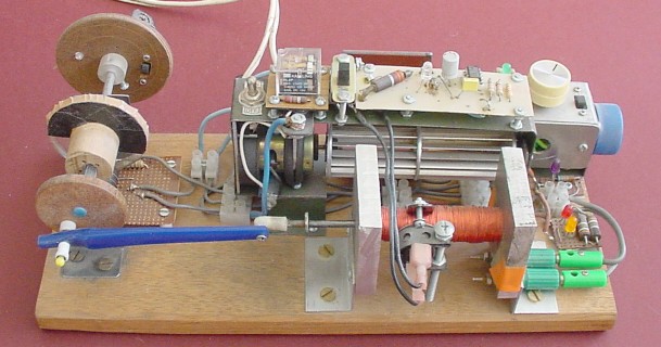
Here is a photograph of the entire model, seen from in front and slightly
above:
Here's a 10-second mpeg movie (921Kb). I start the camera; my wife switches
on the power supply (left, off-screen) and goes around behind me (you'll
notice a shadow effect as she moves through the light from the window); and
then she turns up the speed-control potentiometer to maximum. (The other
potentiometer, used for "fine-tuning" the engine's performance, is set to a
position which is an acceptable compromise for the engine's speed between
the minimum and maximum settings for this movie.) The rotor spins
anticlockwise, as can be clearly seen for the first few seconds; as it picks
up speed, the camera's strobe effect makes it seem to rotate clockwise:
sol-eng1.mpg
Next (also as promised) some comments about the thermostat-controlled
cooling system.
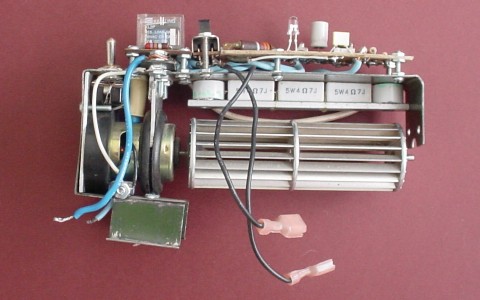
I went a bit crazy with this. The basic idea was to use a fan from an old
hand-held hair-dryer to blow air over the solenoid and thus cool it down.
Here are two pictures of the fan unit, from in front and above:
Here we go - fasten your seat-belt!
You may have noticed a small U-shaped white wire link joining two
terminal-block connections together, near to the power terminals (red and
black) on the main unit. These connections are marked A and B on the circuit
diagram. If this connection is broken, the yellow LED and the LDR are
isolated from the positive rail, so that the transistor is switched off and
the solenoid draws virtually no power - thus the engine stops.
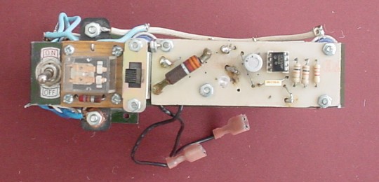
You'll notice that there are two switches on the fan unit. The left-hand one
(with ON and OFF markings) is an SPST (single-pole single-throw) toggle
switch which connects between A and B when the fan unit is installed. This
gives an immediate manual control over the engine's operation.
To the immediate right of this switch is a DPDT (double-pole double-throw)
relay. One pole's "normally-on" contacts are wired to A and B also, so that
if the relay switches on (and the SPST switch is in the "OFF" position), the
engine will stop. (If the switch is in the "ON" position, the relay's effect
is over-ridden, and the engine will continue to operate.)
The "normally off" contacts of this pole operate the fan. When the relay
switches on, it may in turn switch the fan on - depending on the position of
another switch just to the right of the relay.
This second switch is a DPDT slider switch with a central OFF position. With
the slider in that central OFF position, the relay stays off even if the
thermostat triggers. However, with the slider pulled toward you, the relay -
and fan - will come on if the thermostat triggers.
If the slider is pushed away from you, the relay and fan switch on whether
the thermostat has triggered or not.
All this requires only one of the slider switch's poles. The other pole is
used to control a little electronic circuit, which takes up the rest of the
space on top of the fan unit.
This circuit is an astable multivibrator, based on a 555 timer IC, which
flashes a blue LED (this appears clear when off). With the slider in the
central OFF position, the circuit is off and the LED is not illuminated.
With it toward you, the multivibrator is switched on and the LED's cathode
is connected (vai a 2.2K current-limiting resistor) to the 555's output (pin
3) by means of the relay's second pole "normally closed" contacts. The LED
then flashes (about once per second).
With the slider pushed away from you, essentially we introduce a bypass for
the thermostat, so that the relay switches on and its second pole's
"normally off" contacts connect the LED's cathode directly to supply
negative, so that the LED glows continuously. (Recall that the relay's first
pole is then operating the fan.)
The effect of all this is that, with the slider towards you, the fan is in
"standby" mode with the blue LED flashing to indicate this. When the
thermostat triggers (or, equivalently, when the slider is pushed away from
you), the fan operates with the blue LED shining brightly as it does so.
(You are following all this, aren't you?)
To summarize:
The thermostat switch (clamped to the coil) is normally open, and closes at
about 60 degrees C (quite hot!). So, when the coil gets hot, the thermostat
triggers, thus switching on the relay. If the slider is toward you (so that
the blue LED is flashing) when the thermostat triggers, the fan will operate
and the blue LED will glow continuously. When the coil has cooled down, so
that the thermostat clicks off and the relay contacts return to their
"normally off" condition, the fan stops and the blue LED flashes again. If
the slider is away from you, the fan runs and the blue LED glows
continuously. The SPST toggle switch determines whether the engine runs or
pauses while the fan is operating.
A couple of final points:
As mentioned, the engine requires the highest (or at least the
second-highest) voltage setting of my
old black power supply
. For this reason, it was necessary to include appropriate series resistors
for all the LED's (including the blue one), the power connection to the 555,
and the fan.
The 3.3K resistor (the big one at extreme left of the 555's circuit board)
connected to supply positive takes care of the 555's power requirements; and
that resistor and the additional 2.2K resistor (at extreme right) make
things okay for the blue LED.
The fan is in series with three 5-watt resistors, each 4.7 ohm (for a total
of 14.1 ohms). Since these get quite hot when the fan is running, I've
arranged for the fan to blow over them as well as over the coil, thus
solving both problems at once.
Pretty neat, huh?
Here's the overall circuit diagram for the cooling system:
I'll tell you what: in the dark, with the cooling system on standby - so
that its blue LED is flashing - and all the other LED's (including the
flywheel's white LED) doing their respective things, this project looks
just great.
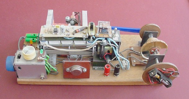
Now, two pictures of the engine with all its components installed, one from
in front...
... and one from behind:
Looks a bit like the old paddle steamer from "Showboat", doesn't it?!
So, what's it all for?
Well, if nothing else, this project shows how an essentially simple idea can
grow into something far more complicated than it has any right to be! But
it's all OK if it's interesting, fun, and part of a learning process.
My home page
Preliminaries (Copyright, Safety)
My single-solenoid electric engine
(ca. 2002)


 This diagram shows the transistor's pinouts. I've used it in its most usual
cofiguration in this circuit: the emitter is connected directly to the
"negative rail"; the collector is connected to one end of the coil (the
other end of which is connected to the "positive rail"); and the base is
connected to reflect what's happening in the LDR.
This diagram shows the transistor's pinouts. I've used it in its most usual
cofiguration in this circuit: the emitter is connected directly to the
"negative rail"; the collector is connected to one end of the coil (the
other end of which is connected to the "positive rail"); and the base is
connected to reflect what's happening in the LDR.
 ). The other end of
this is connected to the wiper of a 5K linear potentiometer; one end of
this is connected to the negative rail and the other end to the LDR. The
other lead from the LDR is connected to the positive rail. Thus the LDR and
the potentiometer together act as a potential divider, which allows
the voltage on the transistor's base to be controlled over a fairly wide
range, thus providing a speed control for the engine. (The 200 ohm resistor
is probably not strictly necessary, but was included as a current-limiting
device just in case.)
). The other end of
this is connected to the wiper of a 5K linear potentiometer; one end of
this is connected to the negative rail and the other end to the LDR. The
other lead from the LDR is connected to the positive rail. Thus the LDR and
the potentiometer together act as a potential divider, which allows
the voltage on the transistor's base to be controlled over a fairly wide
range, thus providing a speed control for the engine. (The 200 ohm resistor
is probably not strictly necessary, but was included as a current-limiting
device just in case.)
 Return to Electromechanical models sub-menu