
When I began this website in early 2005, it wasn't my intention to have a
page devoted to "electromagnetic theory". I wanted the "Electrical stuff"
pages to have a strong "hands-on" feel to them, just like those wonderful
old books to which I keep referring.
However, as I produced more and more electrically-oriented material, I found
that I kept needing to mention some aspect of electromagnetism. I'd intended
to make brief explanatory comments as I went; but I found that the resulting
comments were anything but brief and were making the pages into which they
were inserted long, messy, and tedious - the exact opposite of what I
wanted. Furthermore, I found that I was going to have to repeat myself over
and over again.
So, reluctantly, I eventually decided to "bite the bullet" and include this
page. I've tried to keep it as simple as possible. If you already know a
fair bit about electromagnetism, you can always skip it and continue to the
more obviously practical pages. If you do decide to read on, I hope you find
this page interesting - and there's nothing to stop you trying the
experiments described herein yourself, if you choose!
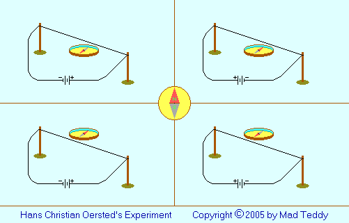
In 1820 (some authors say 1819), the Danish physicist Hans Christian Oersted
(1777-1851) performed a simple experiment. He arranged a piece of wire above
a compass needle and passed an electric current through the wire.
The compass needle was deflected. It ended up pointing not, as you might
expect, parallel to the wire, or even directly at it - but at right-angles
to it.
When Oersted reversed the current, the needle settled down pointing in the
opposite direction.
When the experiment was repeated with the wire was below the needle,
instead of above it, the needle would deflect as before - but this time,
pointing in the opposite direction in each case.
This seems to suggest that something which may be called a "magnetic field"
forms around the wire when a current flows in it. Further experiments
can verify this.
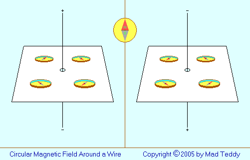
If the wire is positioned vertically, and the compass is moved around it
while current is flowing, the needle will always position itself pointing
skew to the wire, rather than parallel to it or with one of
its ends pointing toward the wire. If the battery positive is
connected to the top end of the wire, and the negative to the bottom end,
the north pole of the needle will point clockwise with respect to the wire
when seen from above - and it will point anticlockwise if the battery
connections are reversed.
If some iron filings are sprinkled on the card (in an arrangement like that
shown above) near to the wire, the current switched on and the card tapped
to reduce friction between the filings and the card, the filings will form a
pattern of concentric circles, again showing the circular nature of the
magnetic field.
Certainly, these are very simple experiments - but with profound
implications. If it weren't for this electromagnetic effect, the
modern technological world as we know it simply couldn't exist. Put it this
way: you wouldn't be reading this on your computer screen right now. There
wouldn't even be any computers!
Just think for a moment what the implications are. (Even if you're an "old
hand" with this stuff, the following may help you to see it all in a fresh
light.)
Firstly, there's a distinctly three-dimensional aspect to this. It's
almost essential to show these effects in some sort of perspective view,
like in the diagrams above, in order to convey a sense of what is going on.
That's unusual; many physical laws can be illustrated adequately using
two-dimensional, or "flat", diagrams.
Secondly, and even more importantly, the whole phenomenon is
asymmetrical. The direction of the magnetic field depends on the
direction of the current. If these directions were parallel (i.e. in the
same dimension), it wouldn't be such a big deal - but that's not the case!
The direction of the current in one dimension determines the direction of
the magnetic field in another dimension. This is an example of
chirality, or "handedness", inherent in the structure of the physical
world.
So far, I've followed pretty much the usual line taken by most physics
textbooks on this subject. The next thing they do, usually, is to consider
what happens if the wire is bent into a loop. Almost immediately thereafter,
the ultimately confusing term "magnetic lines of force" is introduced; this
concept is then extended to deal with what happens with a coil (or
solenoid). Not long after that, depending on the textbook's intended
audience, the concept is either allowed to "fizzle out" as a major issue, or
is tackled by invoking high-powered mathematical tools such as vector
calculus (in Maxwell's equations) - so that the implications of what started
from a very simple empirical observation (Oersted's experiment) become
cloaked in a maze of difficult-to-understand abstraction. How can it get so
complicated, so quickly?
Please - don't get me wrong on this. I'm not pouring scorn on vector
calculus - far from it; it's a powerful and essential tool in many areas.
(Maxwell's contribution was of enormous importance.) My point is that it
is difficult, and it is abstract; and that it should be
possible to present an account of these observed effects which can be
reasonably understood by the lay-person without going to that extreme.
Might it be that the concept of "magnetic lines of force" is more a
hindrance than a help? In fact, I'll stick my neck right out:
Might it be that the very idea of "magnetic lines of force" is in fact
totally wrong?
You've probably gathered that I've got a serious issue with this. If you'd
like to read more on the topic, click
here
. If you'd rather not, that's okay - it's not necessary to do so in order to
get something out of the following pages. You can just continue with this
page for my own development of basic electromagnetic ideas; and you can
always return to the matter later if you become interested.
From comments I've read on other web-pages, I've discovered that I'm far
from the only person in the world who finds the usual "lines of force"
discussion ultimately confusing and unconvincing. So, I feel that I'm in
good company by taking a different tack. My intention in this page is
to sidestep the difficult issues in order to get to a point where we have
enough of an idea of what happens so that a simple discussion of practical
projects becomes possible, without causing any of us a headache. (The link
just given contains my somewhat maverick attempt to deal with the tricky
stuff. As mentioned, you can always have a look at it later.)
On the face of it, a circular magnetic field around a piece of wire doesn't
look particularly useful. After all, ordinary magnets have two "ends", or
poles: a north pole and a south pole. How can we build on Oersted's work to
develop something like that?
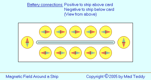
As a first step, suppose we use a flat, wide strip of metal (a knife, for
example) as our conductor, rather than a piece of thin wire. We cut a slot
in a piece of card, run the strip though it vertically, connect a battery to
its ends, and track the magnetic field with a compass, as before. What
happens?
The magnetic field is still there; but now its cross-section (in the plane
of the card) is somewhat "sausage-shaped" (dare we say "cigar-shaped"
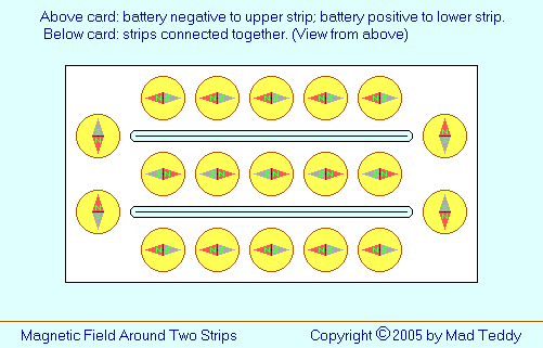
Now, suppose we have two such strips, inserted through two parallel
slots a short distance apart. Above the card, we connect the battery
negative to one strip, and the battery positive to the other; below the
card, we connect the strips together:
For the moment, let's ignore what's happening between the strips, and
compare the effect around the outside of the strips to what happens
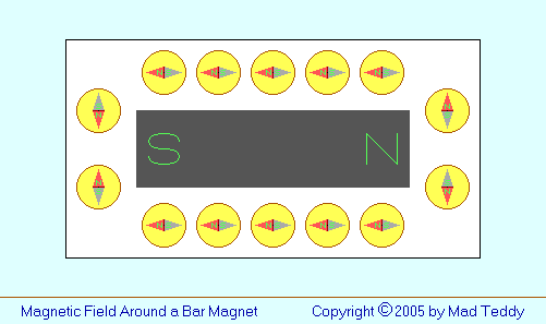
if we move a compass around a simple bar magnet:
Now, I know that this is perhaps somewhat of a simplification of what you
would really see. You'd expect the needles of the compasses located
centrally on the upper and lower sides of the magnet to point horizontally,
as shown; but it's unlikely that any of the other compass needles would
point exactly horizontally or vertically, as suggested here. However, I
submit that this diagram represents a reasonable approximation to a
real situation - good enough to make the point that the magnetic field
around the two strips, where they pass through the card in the previous
diagram, is very similar to that around a bar magnet.
Let's return to the two strips. Suppose that each of them is cut lengthwise
into thinner strips which are laid out parallel to each other like the
original wide strip, with their ends connected together. (Equivalently, you
can consider that the original strips have had narrow lengthwise slits cut
in them, not quite reaching their ends.)
If the experiment with the compass is repeated, we'll still get essentially
the same result. The small gaps will not make any significant difference;
the compass needle will - with possible very small variations near the slits
- point in the same general direction as before at corresponding points.
It's a small step from here to replace the strips with a coil made up of a
single very thin strip. In fact, we can use a long piece of insulated wire.
The current along each turn of the coil (or solenoid) will tend to
reinforce the same overall pattern as with the original strips.
If a rod of iron or some other "ferromagnetic" material is brought near to
the solenoid, the magnetic field concentrated inside the solenoid will tend
to draw the rod in. (This is exactly the principle of operation of my two
solenoid motors, presented in later pages in this website.)
If the coil is wound onto a rod of ferromagnetic material as a permanent
feature, the entire thing becomes an electric magnet, or
electromagnet. If it's operating on direct current (DC), it behaves
very much like a permanent magnet. If the current in the coil varies in some
way over time, things get very interesting and useful. Such coils form the
basis for such "moving-coil" devices as electrical meters, loudspeakers, and
simple electric motors.
Note that this whole discussion has relied only on observations like
those in Dr. Oersted's original experiment with a compass needle. The
concept of a magnetic field has been used, rather carefully - but at
no point has it been necessary to invoke the troublesome notion of "lines of
force".
This link
is worth a look - a cheeky and slightly different take on my basic theme.
Also, before going further, I invite you to click on
this link
to fill in a little more detail about how Oersted made his discovery - and
also to get some idea of how Ampère's important observations fit into the
story.
It's rather alarming, isn't it - Oersted's discovery of the electromagnetic
effect was accidental, or serendipidous. If he hadn't happened to
have a compass needle on the bench, and hadn't happened to see it twitch, we
might all still be living in the horse-and-buggy era and lighting our houses
with candles!
So far, we've considered how an electric current can produce a
magnetic field. Next, it's necessary to consider the other side of
the coin: how a magnetic field can give rise to an electric
current.
Now, I'm going to ask you to do me a favour:
I've found some rather good websites which do a really good job of
explaining electromagnetic induction - certainly at least as good as
anything I could do. To save this page from unnecessarily blowing out into a
monster, would you mind clicking on these links to get the most important
parts of the story?
Also, if you ever happen to notice that any of these links no longer works,
perhaps you could
contact me
so that I can take appropriate action and effect a repair job to this page.
Thanks!
In 1831, English scientist
Michael Faraday
(1791-1867) performed a series of experiments which showed that under
certain conditions, an electric current could be generated using a magnet
and a coil of wire.
By this time, as a result of Oersted's work, it became possible for simple
electric meters called
galvanometers
to be made. André-Marie Ampère (1775-1836), after whom the unit of electric
current is named, is credited with the invention of the first one in 1824.
Faraday's experiments
involved a galvanometer, a magnet, and coils of wire.
That last link mentions how it's possible to arrange two loops of wire so
that a current in one will induce a current in the other. This is the
basic principle of a transformer. Faraday made some
primitive transformers
with which he was able to show electromagnetic induction without the
need to physically move anything.
Here
is a good link which discusses, fairly simply, the basic principle of a
transformer. There is a bit of algebra; if you're the sort of person who
finds that confusing, don't worry - the main idea is that (allowing for some
inevitable losses due mainly to heating) the voltage induced in the
secondary winding will be equal to the voltage across the primary winding
times the "turns ratio" - the number of turns in the secondary divided by
the number of turns in the primary. If the voltage is thus increased,
the current will decrease in the same proportion; and vice versa.
Since power equals voltage times current, the power will stay the
same (again, allowing for some losses).
(While you're there, have a look at some of the other links within the
page - in particular the "solenoid magnetic field" link.)
Okay - the third of those last five excellent links mentions something
called Lenz's Law. We need to take a more careful look at this, because it
has relevance for some of my projects described in later pages. Have a look
at
this web-page
to see a very simple introduction to Lenz's Law.
Heinrich Friedrich Emil Lenz (1804-1865)
was the first person to realize that
"the induced current is such as to oppose the change in the
applied field."
What this means is that, if you insert a magnet into a solenoid, thus
producing a current in the windings, that current creates a magnetic field
of its own which acts in the opposite direction to the magnet's
field.
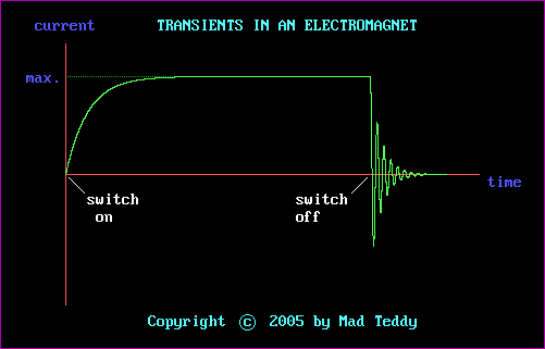
A similar principle applies to electromagnets and transformers. When you
switch on an electromagnet, initially there is a fairly heavy current. The
magnetic field builds up over a short time (it's not instantaneous); and as
it does so, it "tries" to induce a current in the coil which is in the
opposite direction to the current causing the magnetic field in the first
place. The result is that, for a short time, the current will increase
towards its natural maximum value (determined by the supply voltage and the
resistance of the wire) - but it will do so more and more slowly. In
theory, it will never quite reach that maximum possible value, because the
opposing current - though decreasing - is always present. In practical
terms, however, the "main" current can be considered to reach that
maximum value after a fairly short delay. This short-term event is called a
transient.
When the electromagnet is switched off, another transient occurs - but a
dramatically different one. The following diagram illustrates both
transients:
That second transient is pretty spectacular, isn't it? What's going on?
When the current is switched on, energy is being fed into the electromagnet.
For as long as the coil is switched on, that energy is manifested as the
magnetic field.
When the current is switched off, that energy is still there - it doesn't
just disappear. As the magnetic field collapses over a short time, a voltage
appears across the windings, according to the principle of electromagnetic
induction discovered by Faraday (see above). Because of the rapidity of the
collapse - far quicker than the earlier build-up - this voltage is much
greater than the battery voltage while the magnetic field was being
maintained.
The process is akin to pushing a magnet into a solenoid rather slowly, and
then waggling it backwards and forwards very quickly within the solenoid,
with ever-decreasing strokes.
Why does the voltage after switch-off oscillate up and down?
It's all to do with Lenz's Law again. The voltage across the coil generates
another magnetic field, in the opposite direction. This second field reaches
a maximum, then collapses also - thus inducing another voltage across
the coil, which then results in another magnetic field - and so on,
with exponentially decreasing maximum values, until all the energy is
dissipated. The result is a damped sinusoid. (Again, in theory, the
process never finishes; but in reality, of course, it does, as losses occur
all the time.)
A few reasonably simple comments about the frequency of the damped
sinusoid:
The fact that the process is not instantaneous (even though it's pretty
fast) is due to the coil's built-in stray capacitance. To a very
small extent, adjacent turns in the coil behave like the plates of a
capacitor, so that the coil may be thought of as an inductor in
series with this "overall" capacitor. Such an arrangement has its own
resonant frequency, which determines the rate at which the
oscillations occur. The frequency is given by
f = 1 / (2 x pi x (square root of L x C))
where L is the inductance of the coil in henrys, named after
Joseph Henry (1797-1878)
, and C is the capacitance in farads. In simple terms, large inductances and
capacitances lead to low frequencies, and small inductances and capacitances
lead to high frequencies. (In an
induction coil
, high frequencies are desirable because they give rise to higher-voltage
sparks from the secondary.)
The voltages generated - initially at least - may well be high enough to
produce a series of sparks across the switch contacts. (They look like a
single spark to a human observer, because they occur too rapidly for the eye
to see them individually - but suitable photographic techniques may show
what is really happening.) Really high-voltage sparks can be put to good use
- notably, in a car ignition system - but this arcing across the contacts
is a nuisance, partly because it causes damage due to oxidation. There are
ways to deal with it. You can read more about the details of this in my
later page about
induction coils
, which has links to some of my wacky little projects.
There's one more aspect of electromagnetic induction that needs to be
mentioned before we finish.
As already mentioned, there are always some losses in transformers. These
are due to a number of factors, including the resistance of the winding-wire
itself; less-than-perfect "coupling" within and between the coils; - and
eddy currents.
An electromagnet - i.e. a coil of wire wound onto a core of ferromagnetic
material - can generate a more intense magnetic field than a solenoid can.
The iron or similar material has the effect of concentrating the field more
tightly.
However, the very presence of the core can cause problems. If it's made of a
conducting material, and a varying power supply is used (for example, to run
a transformer), the changing magnetic field in the windings will induce
swirling currents in the core itself. As a result, energy that you'd
normally want to be increasing the magnetic field strength (so as to
generate a stronger output from a secondary coil, in a transformer) is going
to waste - and, furthermore, having the undesirable effect of heating the
whole thing up.
Eddy currents are not always a bad thing. If you want a heating
effect, they're a very good thing. In electric furnaces and inductive
hot-plates for cooking, the effect is deliberately promoted.
However, in most situations they're a nuisance. Various measures are often
employed to eliminate or at least minimize the problem.
If you've ever looked at an ordinary transformer, you'll have noticed that
the core is made up from thin pieces of sheet metal. Each of these is coated
with some insulating material, and the whole bundle riveted or bolted
together. Eddy currents will still occur in each individual slice; but
overall, it's an effective way of keeping the losses down quite a lot.
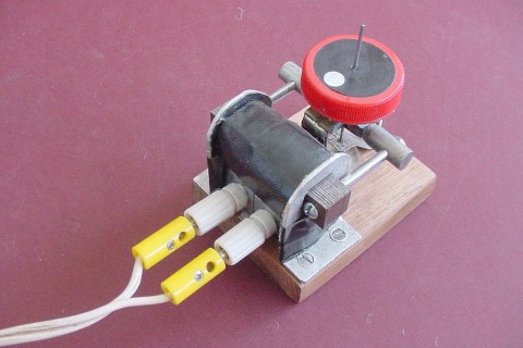
You can see this in the following photograph of my little
synchronous wheel
. The former for the electromagnet was made from part of the core of an old
transformer; the laminations (each about 1mm thick) are clearly visible.
In some special-purpose transformers and other applications, special
non-conductive materials are used. For example, in the flyback (or
line-output) transformer in a TV or computer monitor (a smallish but quite
gutsy transformer which produces the high voltages needed to operate the
picture-tube electron guns), the core is made from a
ferrite
- a salt of what would be
ferrous acid
, H2
Fe2
O4 ,
if it existed (it's unstable and can't be isolated). The material is an
insulator, but it's also ferromagnetic - ideal for the job if you really
don't want eddy currents. (There are other similar materials that can be
used also.)
As you'll see in my
induction coil pages
, normally you do want to minimize eddy currents - but, in one of my
projects of this type, they're not such a bad thing, in moderation. The core
of one of my induction coils was deliberately made from a solid iron rod.
Why? Well, you'll have to read the
relevant page
to find out!
A final comment on this, if I may:
I think it's sad that I wasn't born into an era when I could have been the
discoverer of eddy currents. "Why's that?" I hear you cry. Well, because
then I could have called them "Teddy currents", couldn't I?!
That'll do! Hopefully as a result of reading this, you've got some idea of
what electromagnetism is all about. Don't worry if you don't understand it
all. As I've hinted earlier in this page, I suspect that nobody really does!
After nearly two hundred years, even though we know how to use the effects
to make the quality of our lives better than ever before, there still seem
to be lots of vexed issues.
But is that such a bad thing? Wouldn't it be a boring old universe if we all
knew everything about everything, with no more questions to ask? If teachers
knew all the answers, how would nerdy kids like me piss them off? Who wants
that?
No thanks - that would be a "Nerd's Nightmare"!
My home page
Preliminaries (Copyright, Safety)
Electromagnetism - an introduction



 ?), rather than circular.





 Return to Electrical stuff menu

