
Mad Teddy's web-pages
My dual-solenoid electric engine
(ca. 2002)
If you've had a look at the previous page in this section, in which I described my single-solenoid electric engine , you may recall that whereas "Model Making for Young Physicists" by A.D.Bulman describes a single-solenoid engine (which provided the inspiration for my model), "The Boy Electrician" by Alfred P. Morgan describes an engine which used two electromagnets (rather than solenoids) to produce a double-acting engine. (Actually, Bulman did suggest designing and building a dual-solenoid variation also, but "left it to the reader as an exercise", as the saying goes.)
You may also recall that the original single-solenoid engine my Dad and I built in the late 1960's utilized an old solenoid he had lying around. When the engine turned out to be less than brilliant in its operation, the solenoid was appropriated for other things and subsequently disappeared - only to turn up, finally, among my old Meccano parts in 2002!
By then, I'd built another single-solenoid engine using a home-wound solenoid; so I had this old thing on my hands without an obvious use for it. I put it where I knew I could find it, and moved on to other matters.
Then, a few months later, while hunting around through my Dad's old things, I found a strange device which I recalled had intrigued me as a teenager. This clunky gadget looked as though it might once have seen service as some kind of relay - a magnetically-operated switch. This time, however, the more familiar (to modern eyes) small electromagnet was replaced by a rather gutsy solenoid, quite a bit bigger and more powerful than the other one mentioned above. Here's a view of it (ignore all the other bits'n'pieces on and around it for the moment):
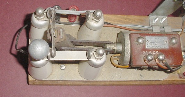
Hmm... I probably should have dusted it off a bit before taking the
picture...
The solenoid operates a T-shaped structure which is attached to the base-plate by a pivot at its lower extremity. The cross-piece of the "T" is a metal bar with rounded contacts on each side of each end.
There are four lovely old-fashioned white porcelain frustrum-shaped towers, each with contacts for the "T" to contact in its travels back and forth. On one side (the nearer side in the picture), the two contacts are connected together by a metal bar.
Three of these four contacts are attached to their respective towers by means of dome-nuts. The remaining one has, instead, a metal ball about 1.9cm (3/4") in diameter. Might the unit have had some high-voltage application once...?
Inside the solenoid itself was a quite strong compression spring which kept the "T" firmly in contact with the left-most tower contacts (as seen in the picture). To push it manually to the right required quite a bit of force. However, if I connected the solenoid to our old black power supply set to 20V AC, it would pull the "T" very smartly to the right so that it would slam into the right-hand contacts with a resounding "clank". Switching off would result in an equally impressive "clunk" as the spring sent the "T" flying back into the left-hand contacts. Whatever this weird gadget might have been used for, it looks as though it must have meant business!
Well, I'm sure you can guess the rest. Here I was, with two solenoids on my hands, one equipped with a ready-made built-in double-throw break-before-make switch. What would you do with them?
Here's a picture of the creation which resulted - and I'll bet you've never seen anything quite like this:
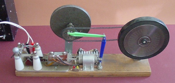
Now you can see the switching-solenoid in context. (You can also see the old black power supply over to the left.) Note that the machine's power terminals are red (for positive) and black (for negative); it requires DC, so my bridge rectifier is also involved (off-screen).
To the right of the switching-solenoid just described is a smaller solenoid. You've guessed it - that's the old solenoid which my Dad and I originally used for our "Mark 1" single-solenoid engine, and which had been lurking for years among my old Meccano parts. Well, now I had something more exciting for it to do!
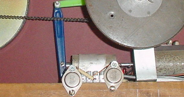
Here you see both solenoids close up.
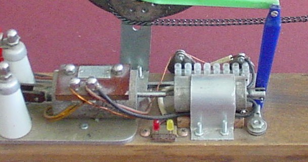
The solenoids are placed "back-to-back". There is a small hole in the end of each case; these holes are of different sizes, but I made up a special linking pushrod from a nail (for the smaller solenoid) and a piece cut from a telescopic TV antenna (for the larger solenoid). By this means, when each solenoid operates, it pushes the other one's core out. Thus the cores and the pushrod shuttle back and forth while the engine is operating.
The small solenoid's core is pivoted to a drilled blue toothbrush handle which forms the armature of the engine. This armature is held at its lower end to the wooden base by another pivot, and connected at its upper end to a connecting rod - made from a green toothbrush handle - by a third pivot. This "con-rod" is pivoted at its other end to a sprocket wheel, which acts a crank, on the engine's axle; thus the back-and-forth (reciprocating) motion of the armature is transformed into rotary motion of the axle. (Scroll back up to the previous picture to see this.)
The large wheel on the axle is part of the tuning system for an archaic radio! It's basically only thin sheet metal, so it doesn't provide much of a flywheel effect.
The other large wheel, on the right, is the turntable from a small record-player I bought for $10 from a fellow-student in 1971, my first year at university in Hobart. The record-player has long-since become obsolete, but - as is my wont - I kept all the bits. So, Tim, if you're reading this, now you know what happened to the old thing!
This turntable is fairly heavy and provides good flywheel action. Since I
had two sprocket wheels (both from my Dad's collection - where else?
 ), it would have been silly not to use them, wouldn't it? The sprocket chain
which passes over them is - in case you haven't guessed - from my old
Meccano parts.
(Fortunately, the sprocket wheels were compatible with a
Meccano sprocket chain, part no. 94 - what a bit of luck!)
), it would have been silly not to use them, wouldn't it? The sprocket chain
which passes over them is - in case you haven't guessed - from my old
Meccano parts.
(Fortunately, the sprocket wheels were compatible with a
Meccano sprocket chain, part no. 94 - what a bit of luck!)
Here's a view of the engine from behind:

The odd-looking arrangement on the support for the turntable / flywheel is there to help stablize the chain. At high revs (and this engine can get moving!), the chain may develop chaotic motions and come off. The bolt in the horizontal metal strip passes through a washer, a small plastic spacer cut from an old ball-point pen, another washer, and a nut before being lock-nutted to the strip; the spacer presses lightly up under the chain and stabilizes it enough so that the chain stays on (usually!) - at least when the wheels are spinning clockwise (as seen from the front).
The engine can work almost equally well in either direction, although slightly better clockwise. If it's running anticlockwise, the chain still comes off sometimes. I probably ought to have a similar arrangement pressing down on the top part of the chain to help prevent that also. I'll get around to it one day...
Here's a view of the engine from above:
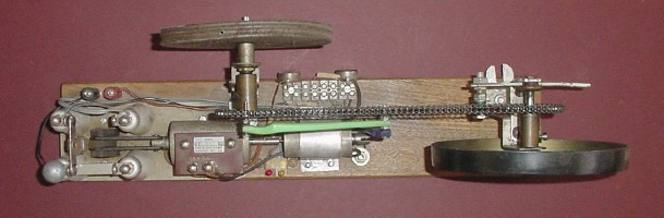
Now, we come to the most interesting part of the whole project. How does the big solenoid's switching system operate to allow each solenoid to operate at exactly the right time, and alternate between them?
By now you will have noticed a small gadget attached to the wooden base just behind the small solenoid. This is a bistable multivibrator, or "flip-flop".
The flip-flop is made up from two 2N3055 transistors; two 1K (1,000-ohm) resistors; and two LED's (light-emitting diodes), one red and one yellow. All except the LED's are mounted in a terminal block. The structure is attached to the base by two screws, each through a hole in the case of one of the transistors. The LED's are mounted separately on a small piece of stripboard near the front of the base, and connected to the terminal block by short wires.
The following diagram shows the flip-flop as seen from above. Note that the emitters of both transistors are at the extreme ends of the terminal block, with their bases connected to the switching contacts and their collectors (the transistor bodies) connected to the solenoids.
Each transistor is of the NPN (negative-positive-negative) type. If a nett positive voltage is applied to the base, current can flow readily through the transistor via its collector and emitter. If the base voltage is negative, almost no current can flow.
The left-hand diagram below shows the pinouts of the 2N3055 transistor. To its right is a full circuit diagram of the entire engine. (You can click on this to see a version which attempts to show the switching system in more detail.)

So, how does it work?
Assume for the sake of argument that the "T" is initially over to the left (in the nature of things, this is the normal starting position - mainly because when the engine is switched off, the "T" ends up on the left). At switch-on, for a brief moment, enough current may pass through the yellow LED to light it - but the moment is so brief that there's no visible flash.
As the base of Q2 is connected to supply negative, Q2 is off (i.e. no appreciable current flows through it from its collector to its emitter). Thus current flows preferentially through the red LED and its 1K series resistor, bringing the base of Q1 close to supply positive (via the small solenoid). Hence Q1 is switched on - current can flow easily through it from its collector to its emitter.
As a result, a heavy current flows through the large solenoid - far more than through the small one. So the solenoid cores and the pushrod start to move to the right. Since current is now flowing preferentially through the relatively small resistance provided by the large solenoid, very little current flows through the series combination of the yellow LED and its IK resistor - certainly not enough to keep the LED glowing. This all happens very quickly, so that the yellow LED is only on for a tiny fraction of a second.
Note: As soon as the "T" starts to move, the yellow LED is disconnected from the supply negative. Even if this were not the case, however, the yellow LED wouldn't glow anyway - because the series resistance of the LED and its 1K resistor is considerably greater than that of the large solenoid / Q1 combination, which thus receives the lion's share of the available current.
Although the contact is broken, the transistors keep each other in that pattern while the "T" moves across. However, as soon as it touches the right-hand contact, the situation changes dramatically. The base of Q1 is connected directly to supply negative, so that Q1 switches off. As a result, the now quite small current flowing through the large solenoid goes preferentially through the yellow LED and its 1K resistor, producing a nett positive voltage at the base of Q2. Thus Q2 switches on, allowing a heavy current to go through the small solenoid - so that the cores and the pushrod start moving to the left again...
And the beat, as the saying goes, goes on!
As the circuit "flips" and "flops" backwards and forwards, the solenoids cause the engine's wheels to rotate. (As mentioned earlier, they can rotate in either direction - depending on the crank's position at start-up.) The flip-flop and the switching system together act as a kind of commutator.
The 1K resistors are there to limit the current through the LED's to less than 30mA (milliamps). The currents are still quite sufficient to send the bases positive enough to ensure that the transistors switch on when and as required.
The LED's themselves are just for show, really! The way they are connected,
the red LED is on while the large solenoid is on, and the yellow LED is on
while the small solenoid is on. I just like miniature psychedelic light
shows!
Clever though the design of this gadget may be (even if I do say so myself), it's not quite perfect. When I first made it and started playing with it, it gave me a surprise.
If the crank / con-rod / armature combination is well over to the right at switch-on, the commutator can start to "clatter". The first time this happened, I thought something was broken; but I soon realized what was going on. With the "T" initially over to the left, the large solenoid - with no resistance from the mechanical parts - pulled the "T" rapidly to the right, where it slammed into the right-hand contacts. This, of course, changed the state of the flip-flop (as described above). The combined effect of the small solenoid's operation and the contact-bounce caused by the fast initial movement of the "T" caused it to move to the left, also very quickly, so that the cycle could start again. Quite annoying!
As I played with the machine over time, the clattering got worse, and began to happen even when the crank was at a less extreme initial position. In fact, it began to occur during actual engine operation - there would be an occasional stutter, and sometimes it would stop altogether!
I eventually realized what the cause was. The screw holding the armature's
pivot to the base had gradually worked a bit loose, so that the overall
movement - dominated by the large solenoid - had pushed the linkage to the
right. Only by a whisker, but enough to make quite a difference in
performance. The reason the engine sometimes actually stopped was that the
"T" didn't always quite make it back to the left-hand contacts. (I hope
you're following all this, because there's going to be a short test on this
engine's operation and possible technical faults at the end of the page!
)
The only way to fix the problem permanently would be to somehow bond both of the cores to the pushrod, so that they would have to move as a single unit at all times. Apart from the obvious difficulty of doing this, I wouldn't want to, because the integrity of the original components would thus be spoiled. So I'll just put up with it, and treat it as a worthwhile experimental observation in its own right.
Once, the engine gave me another surprise - an even bigger one. I was interested to see whether the transistors became warm during operation; so I reached over the model with my right hand and placed my forefinger on the back of Q1 and my middle finger on the back of Q2 (i.e. on the transistors' collectors). Guess what? I got a SHOCK! No kidding - quite a jolt.
Since the collectors are connected directly to the solenoids, presumably the high-voltage transients caused as each solenoid is switched off once each cycle were responsible for this. (To read more on these high-voltage transients, have a look at my Elecromagnetism - an introduction page.) So, a word to the wise: even with small projects running off fairly low-voltage power supplies, be aware that momentary high voltages may occur at less-than-obvious places and times, and be careful.
(By the way, the transistors weren't hot - well, not temperature-wise, anyway!)
To close this page: a 15-second (1.3Mb) movie of the engine operating. I say "now"; my wife switches it on, and the speed builds up over several seconds.
The engine rotates clockwise in this movie. I've put a spiral graphic onto the flywheel to show the motion clearly. You'll notice that the wheels do indeed appear to rotate clockwise as the engine starts and begins to speed up; but about six seconds into the movie, the stroboscopic effects due to the camera's operation make the engine seem to slow down and start to rotate anticlockwise. (If you've visited my other electromechanical models pages, you'll almost certainly have noticed similar effects there.)
Of course, it's an illusion; you can get a true indication of the engine's behaviour from the noise of the switching-system (and, believe me, it kicks up quite a racket!).
The other thing to note here is a slight "clatter" as described above, about four seconds in - even once the engine has started moving fairly quickly. It was shortly after I took this movie that I figured out that the problem was being caused basically by that loose pivot, and tightened it up. Even though the machine now works better (i.e. with a higher top speed, more rapid acceleration, and little or no clattering) as a direct result, I decided to leave this original movie on the page just to highlight the effects mentioned.
Okay! Here's the movie. Enjoy!
 Return to Electromechanical models sub-menu
My home page Preliminaries (Copyright, Safety)